The 3D Viewer & Outline
How the mesh is drawn
The viewer builds one layer per entity block and one per SubModelPart:
- Nodes, elements, conditions, geometries are all rendered. Point-only data (node clouds, node-set SubModelParts) is drawn as vertex points.
- Volume elements (tetrahedra, hexahedra, wedges, pyramids) are shown as their boundary surface — interior faces shared by two cells are dropped, so you see the outer skin rather than a solid block.
- Quadratic elements are approximated by their corner nodes (the straight-edge hull); mid-edge nodes are not curved.
- When a mesh has both surface blocks and volume blocks, the volume blocks open hidden by default (their boundary usually coincides with the surface blocks) so the viewport isn't doubled up. Tick the volume layer to show it.
The outline tree (Layers)
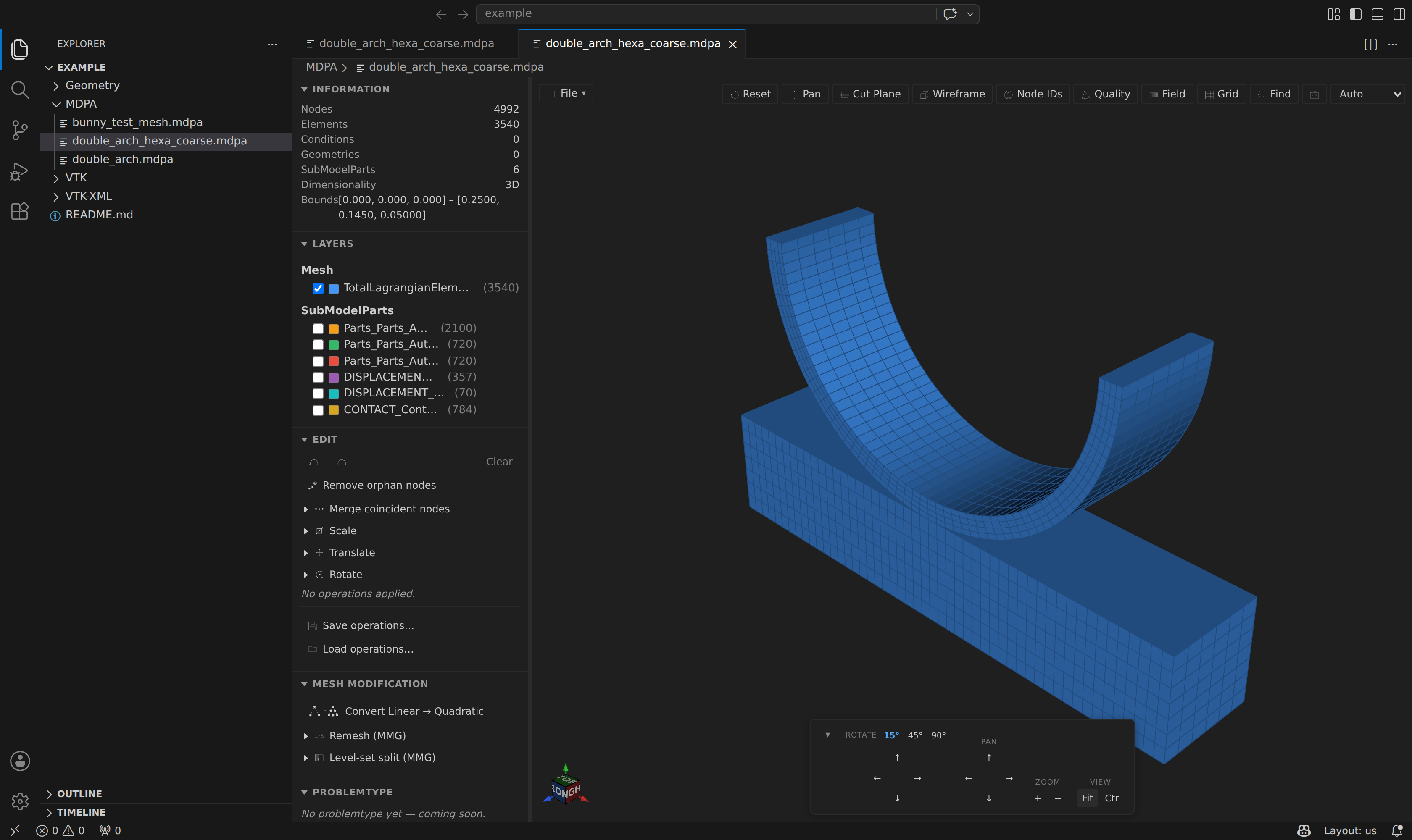
The Layers section lists every layer in two groups:
- Mesh — one row per entity block (e.g.
Element3D4N,SurfaceCondition3D3N), with the block's color swatch and entity count. - SubModelParts — the full SubModelPart hierarchy, nested to any depth.
Each row has:
- a checkbox — activate / deactivate that layer (show / hide it),
- a color swatch — the layer's color in the scene,
- a label — click it to frame (zoom the camera to) that layer,
- an entity count.
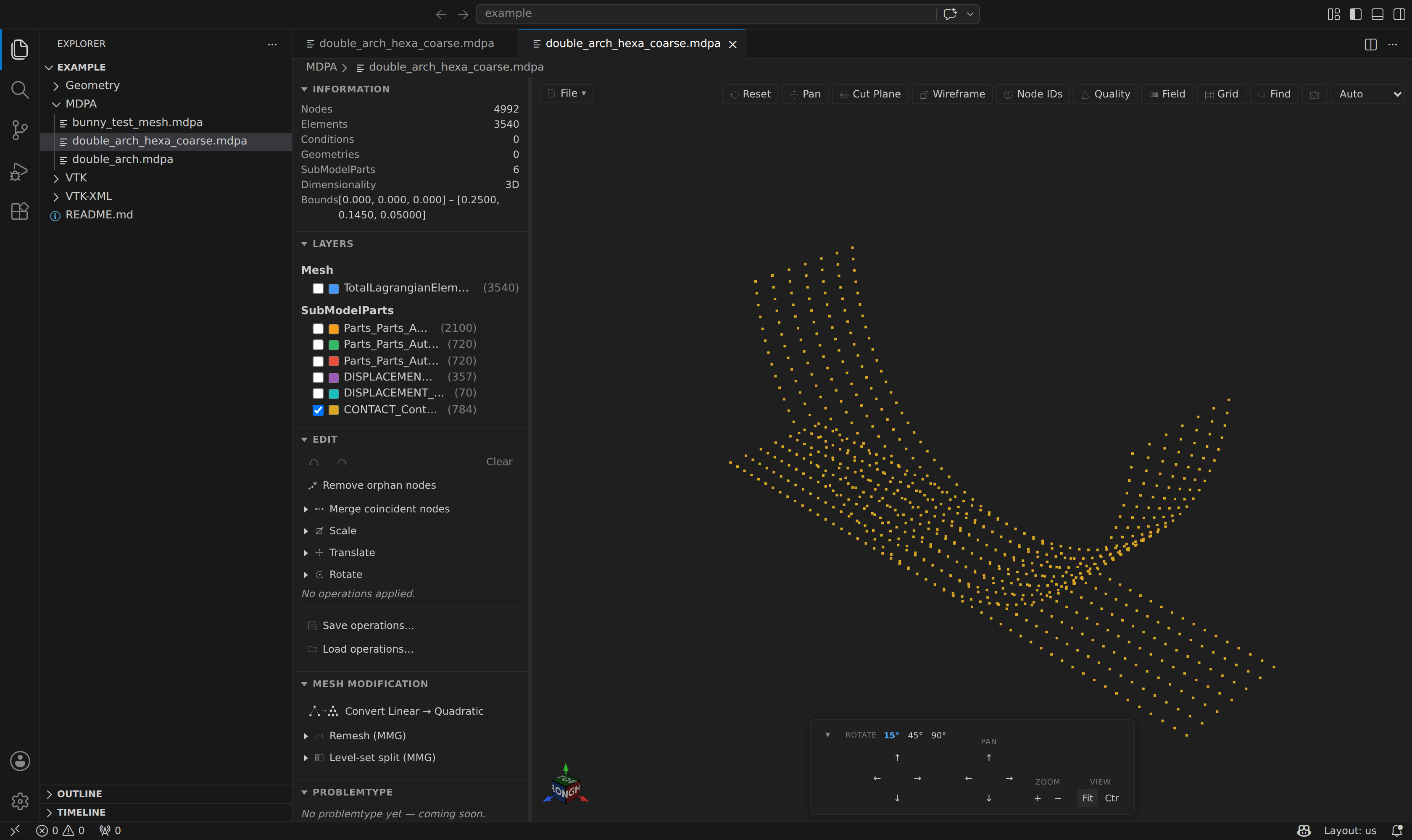
SubModelParts open hidden by default, so you can reveal them one at a time to isolate an inlet, outlet, boundary, or contact surface:
SubModelPart rows also carry two extra buttons:
- an export button — write just that part (and its subtree) to any supported format (see File menu),
- a ✕ delete button — remove the part and its entities from the mesh as an undoable edit (see Mesh Editing & History).
Node-id labels
The Node IDs toolbar button overlays each node's id in the scene. To keep the view legible (and fast) the labels are shown only when the mesh has 1 000 nodes or fewer.
The stats panel
The Information section reports node / element / condition / geometry counts, the number of SubModelParts, the detected 2D / 3D dimensionality, and the mesh bounding box. If a Kratos element type could not be mapped to a drawable VTK cell, its name is listed here rather than silently dropped — a quick way to spot an unusual element in a large file.