Beam / Line Elements
A frame, a truss or a reinforcement cage is not made of triangles — it is made of line elements, each standing for a member with a cross-section. Kratos writes them as TrussElement3D2N, CrLinearBeamElement3D2N and the like.
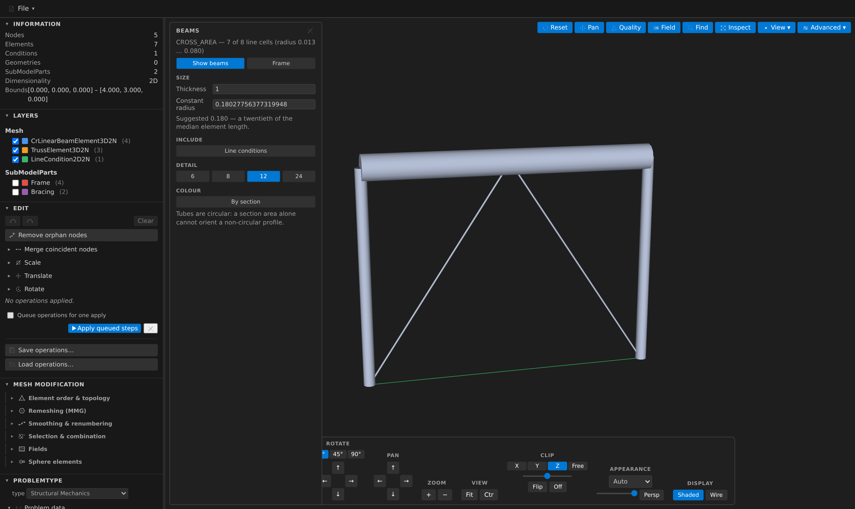
Advanced ▸ Beams… renders them as real tubes instead of hairlines.
Why a dedicated rendering
A line cell has no extent. Left to the ordinary path it draws as a fixed-width screen polyline — the same handful of pixels whether the member is a 6 mm tie rod or a 600 mm girder, and the same width however far you zoom out. A frame of wildly different sections looks like a wireframe of identical sticks.
Tubes are scaled in model space, so they behave like geometry: they grow as you zoom in, a heavy column visibly outweighs a slender brace, and the structure looks like what it is.
Where the section comes from
From the Properties block, when it has one. This is where Kratos actually keeps a member's section — CROSS_AREA, alongside I22, I33 and the rest — and every element row already names the property id it uses. The drawn radius is the circular-equivalent one, sqrt(A / π).
Begin Properties 1
    DENSITY 7850.0
    CROSS_AREA 0.0201
End Properties

Begin Elements CrLinearBeamElement3D2N
1 1 1 2
End Elements
From an ElementalData CROSS_AREA field, if the mesh carries one instead — useful for a mesh that came in through a format with no Properties concept.
From a constant, otherwise. The panel suggests one — a twentieth of the median element length — and draws every sectionless cell at it.
The section is resolved per cell, not per block. That matters more than it looks: repeated Begin Elements <Name> blocks are merged into a single layer, so one layer routinely contains members on several different properties. In the example above, the braces and the tie live in one merged block and still get their own sections.
What is not drawn as a tube
This is the important half. A line cell is also the shape a 2D boundary takes: a LineCondition2D2N skin around a plate, or a WallCondition2D2N around a fluid domain, is topologically identical to a truss. So the rendering turns itself on only when the mesh gives it a reason to:
- The mesh must declare a genuine
CROSS_AREA. A mesh with none — an imported.objwireframe, an extracted edge set, a fluid skin — stays as plain lines. - Only Elements count towards switching it on. A boundary condition routinely references the same property id as the part it bounds, so a condition alone never flips the rendering for the whole mesh.
You can still draw line conditions deliberately: open the panel and turn on Line conditions.
The panel
- Show beams — toggle the tubes. Frame zooms to them.
- Thickness — a multiplier on every tube's radius. The length always stays the element's own, so a member never detaches from its end nodes.
- Constant radius — used for cells with no
CROSS_AREA(and for all of them when the mesh declares none). Prefilled with the suggestion. - Line conditions — also draw line Conditions and Geometries. Off by default, for the reason above.
- Detail — cylinder tessellation (6 / 8 / 12 / 24). Above ~50 000 tubes the panel warns you off the finer settings.
- By section — colour the tubes through the usual colormaps and legend, so a frame with graded members is readable at a glance. Only offered when the sections actually vary.
The tubes follow the deformed-shape warp like every other glyph, so a displaced frame draws displaced members.
Reading the section elsewhere
Properties values are parsed now, so they are also visible headless. The mesh_info MCP tool reports them as a properties section, plus a beams section describing the line cells:
{
  "properties": [{ "id": 1, "values": { "DENSITY": 7850, "CROSS_AREA": 0.0201 } }],
  "beams": { "cells": 8, "sectioned": 7, "elementsSectioned": 6, "suggestedRadius": 0.18 }
}
sectioned counts every line cell that resolves a section; elementsSectioned is the stricter count the viewer gates on. A mesh where the two differ sharply is usually a boundary sharing a structural part's properties.
Limits worth knowing
- Tubes are circular. A section area cannot orient a non-circular profile — an I-beam needs a roll angle about its own axis, which the area alone does not carry.
- A quadratic line draws straight. Its mid node is dropped and the tube chords its two end nodes, exactly as the underlying line already did.
Line2D3andCrLinearBeamElement3D3Nare read as triangles. A name of the form<X>3D3Nis ambiguous —Element3D3Nis a triangle far more often than it is a quadratic beam — and the extension resolves it that way. Only a suffix-less name such asLine3is read as a quadratic edge.- The section is read, not written. There is no operation that edits
CROSS_AREA: it belongs in thePropertiesblock, which a Save emits from the model so the round-trip preserves it. The panel's constant is a viewing aid, not mesh data.