Prepare a part for FEA
This is what CAD Preview is for. The previous tutorials made geometry; this one turns geometry into something a finite-element solver can run: named regions, a graded tetrahedral mesh, and a Kratos MDPA file with those regions carried through as sub-model-parts.
It picks up the bracket from the first tutorial — build that first, or paste its operation list in.
It should take about 20 minutes.
Starting point
The finished bracket: an L-shaped solid with a filleted inside corner and two counterbored bolt holes, 18 faces in total. Its full operation list is repeated at the bottom of this page if you need it.
Step 1 — Name the regions you will apply boundary conditions to
A solver needs to know where things are fixed and where the load goes. In CAD Preview those are parts — named groups of entities, stored in a <model>.parts.json sidecar, never in the CAD file.
- Open the Select ▾ menu in the toolbar, click Selection mode, and choose Surf.
- Click the bracket's underside (the large face at z = −3).
- In the Parts panel, click + New, rename the part to
FixedBase, and click the + on its row to assign the selection. - Repeat for the wall's outer face (at y = −20), naming it
LoadFace. - Repeat once more for the two bolt-hole walls — shift-click to select both — naming it
BoltHoles.
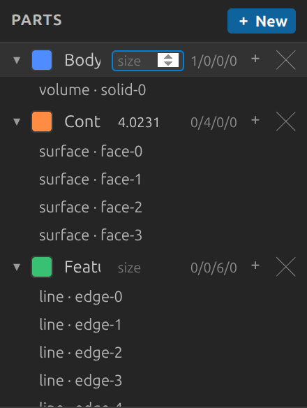
Each part gets a colour, and the assigned faces recolour in the 3D view immediately. If you lose track of which face is which, the hover tooltip names the entity under the cursor.
Step 2 — Refine the mesh where it matters
Bolt holes are where stress concentrates, so they want smaller elements than the rest of the part.
- In the Parts panel, find the
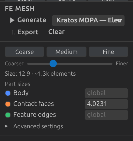
BoltHolesrow and set its mesh size field to1.5. - The same field is mirrored in the FE Mesh panel's Part sizes section — either one works, and they stay in sync.
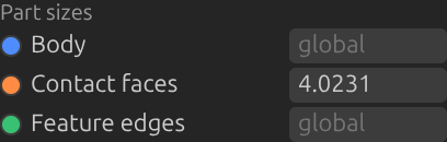
A per-part size becomes a Gmsh sizing field scoped to that part's entities. Where several overlap, the smallest requested size wins; everything unassigned keeps the global size from the next step.
Step 3 — Set the global mesh size and generate
- Open the FE Mesh panel.
- Leave Dimension at
3(a volume mesh of tetrahedra). - Drag the size slider, or use the Coarse / Medium / Fine presets. For this part, a Size max of
4is a reasonable starting point — the readout shows the resulting element estimate as you drag. - Click ▶ Generate.
The mesh appears as an overlay on top of the model, coloured per part — so you can see at a glance that your named regions ended up where you meant them.
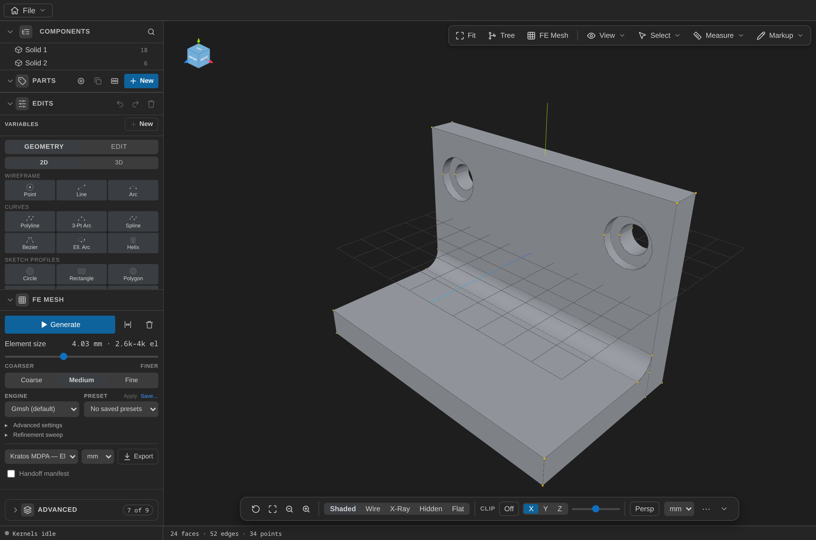
With Size max = 4 and the bolt holes at 1.5, this bracket meshes to roughly 1200 nodes and 3600 elements in well under a second.
Step 4 — Read the quality summary
Under the node and element counts, the panel reports the mesh's minimum and mean element quality plus a histogram. The metric is Gmsh's minSICN, where 1 is an ideal element and 0 is degenerate.
For this bracket you should see a minimum around 0.2 and a mean around 0.75 — healthy for a tetrahedral mesh with a fillet and two holes in it.
If any elements fall below 0.2, a Worst toggle appears next to Clear and lights up automatically. It highlights those elements in red, drawn through the rest of the model so you can see a bad element buried inside the volume rather than only on the surface. Coarsening or refining usually clears them.
Step 5 — Advanced settings, if you need them
Expand Advanced settings for element order and shape.
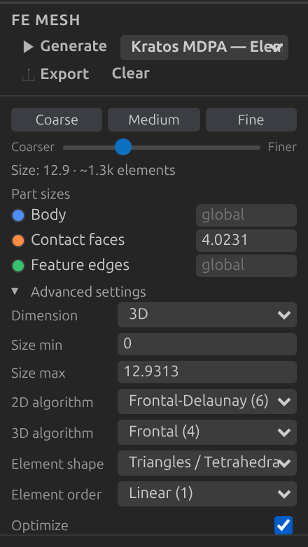
- Element order 2 adds mid-side nodes —
Tetrahedra3D10instead ofTetrahedra3D4. The overlay still draws corner geometry only, so it looks the same; the node count roughly quadruples. - Element shape switches between tetrahedra, hexahedra, and hex-dominant.
Kratos MDPA cannot represent a hex-dominant mesh
Hex-dominant meshing emits a tet/hex transition element that has no Kratos geometry equivalent. The export refuses with a message naming it, rather than writing a file that would fail to load. Gmsh's own formats and VTK handle it fine.
Step 6 — Export for Kratos
- In the FE Mesh panel, choose Kratos MDPA — Elements + Conditions in the export dropdown (it is the default).
- Leave the unit selector at mm unless your solver expects otherwise — it applies a real geometric scale, not a relabelling.
- Click 📤 Export and choose where to save.
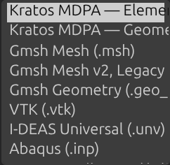
Open the resulting .mdpa in a text editor. Past the Nodes, Elements, and Conditions blocks you will find one sub-model-part per named part:
Begin SubModelPart FixedBase
    Begin SubModelPartNodes
    ...
    Begin SubModelPartElements
    Begin SubModelPartConditions
Those are the handles your Kratos case file references when it applies a fixity or a load. The two export modes differ in how they write the cells: Elements + Conditions writes Element* and Condition* blocks with a property id; Geometries writes a single Geometries container sharing one id space.
Full operation list
The bracket, for reference:
[
  { "op": "addBox", "center": [0, 0, 0], "size": [60, 40, 6] },
  { "op": "addBox", "center": [0, -17, 18], "size": [60, 6, 30] },
  { "op": "boolean", "kind": "union", "a": ["solid-1"], "b": ["solid-2"] },
  { "op": "fillet", "edges": ["edge-13"], "radius": 4 },
  {
    "op": "addCounterboreHole",
    "targets": ["solid-0"],
    "position": [-22, 10, 3],
    "axis": [0, 0, -1],
    "radius": 3,
    "depth": 6,
    "cbRadius": 5,
    "cbDepth": 2
  },
  {
    "op": "addCounterboreHole",
    "targets": ["solid-0"],
    "position": [22, 10, 3],
    "axis": [0, 0, -1],
    "radius": 3,
    "depth": 6,
    "cbRadius": 5,
    "cbDepth": 2
  }
]
The parts and mesh options live in their own sidecars (<model>.parts.json, <model>.mesh.json) rather than in the op list — they are not edits, they are metadata about the model.
What you practiced
- Parts as named entity groups, stored beside the CAD file and never in it.
- Per-part mesh sizing, and the smallest-size-wins rule where regions overlap.
- FE mesh generation, its quality summary, and the worst-element highlight.
- Kratos MDPA export, and how parts become
SubModelPartblocks a case file can reference.
Next: build this same bracket with an AI agent instead of by hand.