A shelled enclosure
The first two tutorials built everything from 3D primitives. This one starts flat: a 2D profile sketch, extruded into a solid, then hollowed with shell into an open-topped box.
That sketch → extrude → shell sequence is the workflow most CAD users reach for first, and it is also the clearest demonstration of what CAD Preview records about each operation — you will read the extrude's own report of which face became the top, which became the bottom, and which are the walls.
It should take about 10 minutes.
Starting point
Open examples/STP/block.stp. The enclosure's floor is thick enough to bury the seed block entirely, so it never pokes through the open top.
Sketches are B-rep only
Profile sketches, extrude, and shell all need exact topology, so they are available for STEP, IGES, and BREP sources only. Open a mesh file (STL, OBJ, PLY, glTF) and the 2D sub-tab greys out with a tooltip saying so.
Step 1 — Draw a rectangle
- In the Edits panel, select the GEOMETRY tab and then the 2D sub-tab.
- Click Rectangle.
- Set Center to
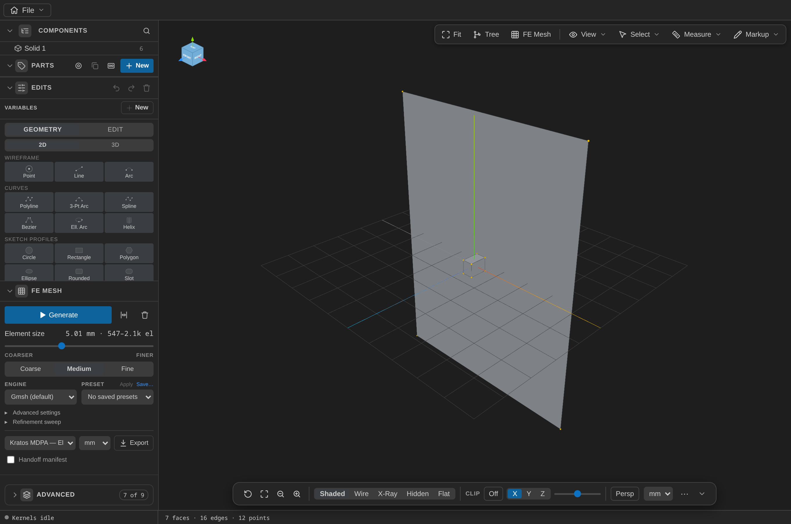
0, 0, -3, Normal to0, 0, 1, Up to0, 1, 0, Width80, Height60. Apply.
Normal is which way the sketch plane faces; Up is which in-plane direction Width runs along. They must not be parallel — the form rejects that rather than guessing.
Look at the Components tree: the new face appears under a group called Sketches, not under a solid. A bare face is not a body, and it is there to be picked and fed into something else.
Step 2 — Extrude it
- Switch to the EDIT tab and click Extrude in the Feature category.
- With Surf selection mode active, click the rectangle in the 3D view — or type
face-6into the Profile field. - Set Direction to
0, 0, 1and Length to48. Apply.
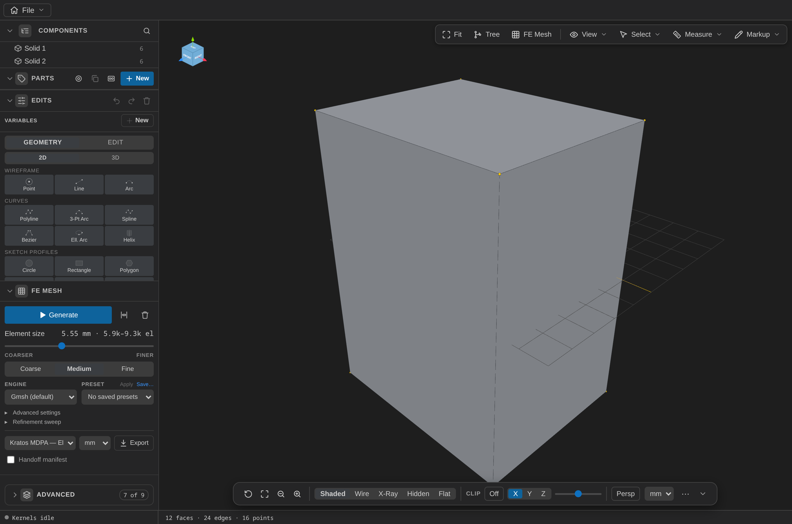
The box now runs from z = −3 to z = 45. The Sketches group is empty again: extrude reuses the profile face as the new solid's bottom cap rather than copying it, so the sketch is consumed, not duplicated.
Step 3 — Read what the extrude produced
Hover the extrude's row in the Edits history. The +6 chip lists the faces it created, grouped by the role each one plays:
| Role | Face | What it is |
|---|---|---|
| start cap | face-10 | the original profile face, at z = −3 |
| end cap | face-11 | the far face, at z = 45 |
| side walls | face-6 … face-9 | the four sides |
Click the chip to flash those faces in the 3D view. This is recorded at the moment the op runs, which is the only time the information is unambiguous — it is what lets you say "the top face" without hunting for its current index.
Step 4 — Hollow it out
- In the EDIT tab, click Shell in the Modify category.
- Set Opening faces to
face-11— the end cap from the table above. - Set Thickness to
-6. Apply.
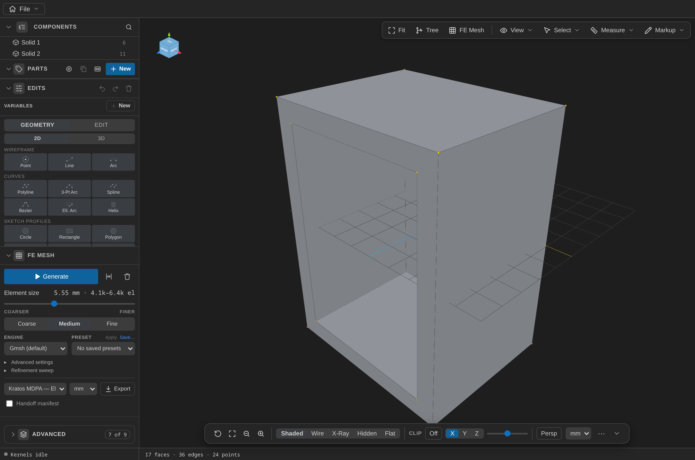
A negative thickness offsets inward, so the outer dimensions stay put and 6 mm of wall is taken from the inside. The result is an open-topped box: 6 mm walls, a 6 mm floor spanning z = −3 to z = 3 — which is exactly what buries the seed block's ±2.5.
Shell needs at least one opening face
With an empty opening list, the operation returns a smaller solid rather than a hollow one — it has nothing to open the cavity through. The form requires at least one face for that reason.
Step 5 — Check it
Enable a clipping plane from the View controls panel's Clip group and sweep it through the box. The cut face renders as a solid cap, so you can see the wall and floor thicknesses directly rather than looking through a hollow shell.
Full operation list
[
  {
    "op": "addRectangleProfile",
    "center": [0, 0, -3],
    "normal": [0, 0, 1],
    "up": [0, 1, 0],
    "width": 80,
    "height": 60
  },
  { "op": "extrude", "profile": "face-6", "dir": [0, 0, 1], "length": 48 },
  { "op": "shell", "thickness": -6, "openingFaces": ["face-11"] }
]
What you practiced
- Profile sketches as first-class, pickable geometry that lives under Sketches until something consumes it.
- The normal / up convention that orients a 2D profile in 3D.
- Extrude, and that it consumes its profile rather than copying it.
- Build-time face roles — what an op reports about the faces it just made.
- Shell, its inward-negative thickness, and its need for an opening face.
Next: prepare a part for FEA, or go back to the bracket.