A parametric bolt-circle flange
This tutorial builds a round flange with a ring of bolt holes — but the hole count and the bolt circle radius are variables, not typed-in numbers. Change N from 8 to 12 and the flange re-drills itself.
Along the way it covers the one technique that trips people up: there is no "pattern this hole" op, because patterns act on solids. The move is to pattern the cutting tool, then subtract the whole set in one go.
It should take about 15 minutes.
Starting point
Open examples/STP/block.stp, as in the first tutorial. The flange disc you add in Step 2 encloses the seed block.
Step 1 — Define the variables
- Open the Edits panel and find the Variables table at the top.
- Click + New, rename the variable to
R, and set its expression to30. - Click + New again, name it
N, and set its expression to8.
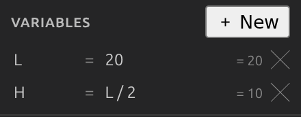
R is the bolt circle radius and N is the hole count. Any numeric field in any op form can hold an expression over these instead of a literal — R/2, 360/N, R*cos(30) all work. Trig takes degrees, matching every angle field in the app.
Variables can build on each other
A variable may reference any variable defined above it in the table. That is what makes derived values like W = L/2 work — and it is also why cycles are impossible to write.
Step 2 — The flange disc
- GEOMETRY ▸ 3D ▸ Cylinder.
- Set Center to
0, 0, -5, Axis to0, 0, 1, Radius40, Height10. Apply.
For a cylinder, Center is the centre of the base circle, not the middle of the body — so this disc runs from z = −5 to z = +5 and swallows the seed block. It becomes solid-1.
Step 3 — One hole, as a cutting tool
- Click Cylinder again.
- Set Center to
30, 0, -10, Axis0, 0, 1, Radius3, Height20. - Before applying, replace the Center X field's
30with the expressionR. - Apply.
This is deliberately taller than the flange (20 mm through a 10 mm disc, starting below it) so it cuts cleanly through both faces. It is a solid like any other — solid-2 — and nothing has been subtracted yet.
Step 4 — Pattern the tool
- EDIT ▸ Assembly ▸ Circular Pattern.
- Set Targets to
solid-2, Axis point0, 0, 0, Axis dir0, 0, 1. - Set Angle to the expression
360/Nand Count to the expressionN. Apply.
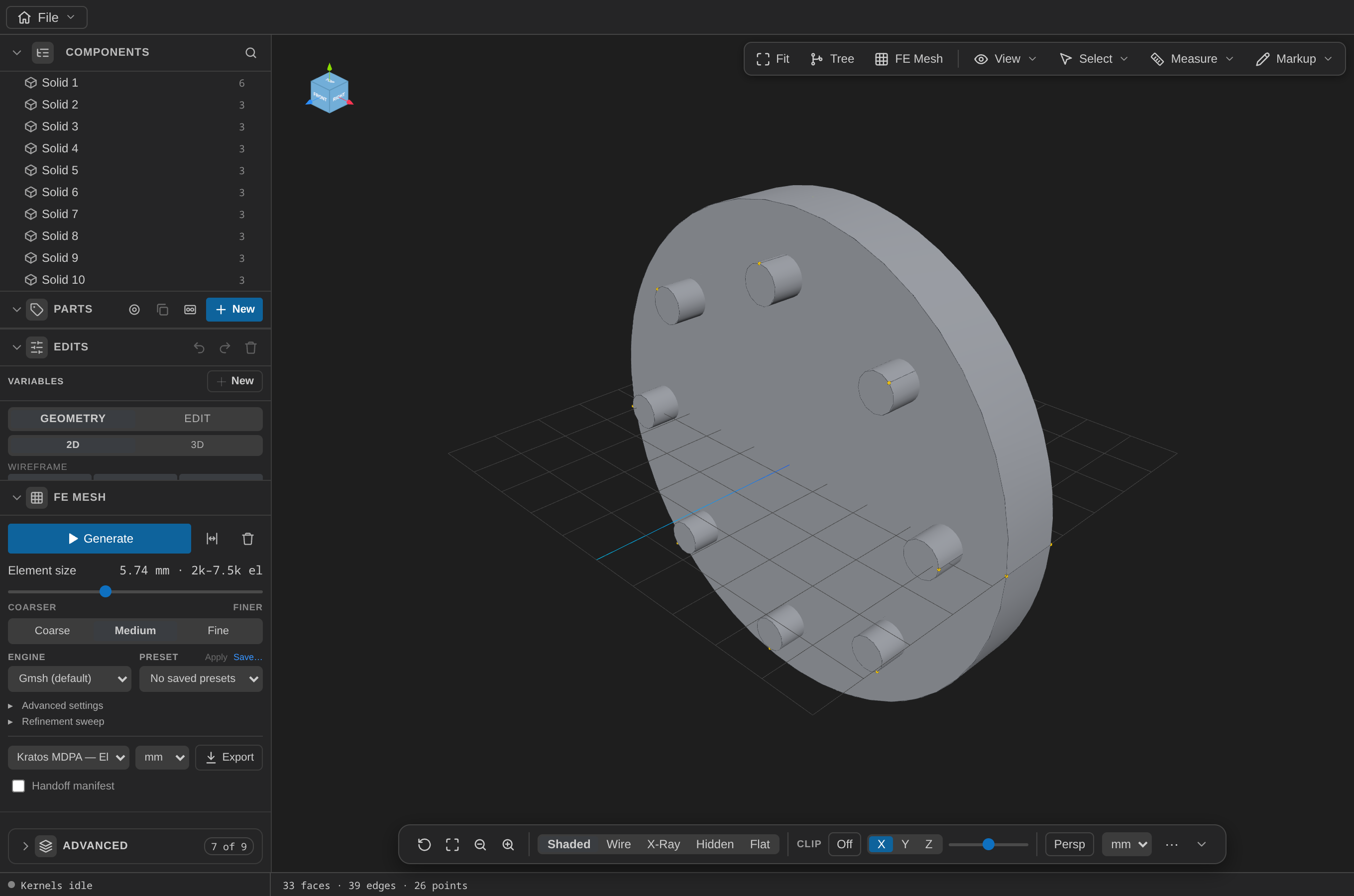
Count is the total number of instances, including the original — so N = 8 gives you the one you made plus 7 copies, solid-2 through solid-9.
Expressions apply on the next read, not mid-op
A plain op's expressions stay live — they are stored as an annotation next to the last computed value, and re-evaluated when the model is read. So the pattern shows 8 tools once the edit list is re-read, which the viewer does for you on every change. If you are driving this over MCP, the resolved count appears in the following load_model, not in the apply_edit_ops response that created it.
Step 5 — Subtract the whole ring at once
- EDIT ▸ Boolean ▸ Subtract.
- Set A to
solid-1(the disc) and B tosolid-2, solid-3, … solid-9(all eight tools). - Apply.
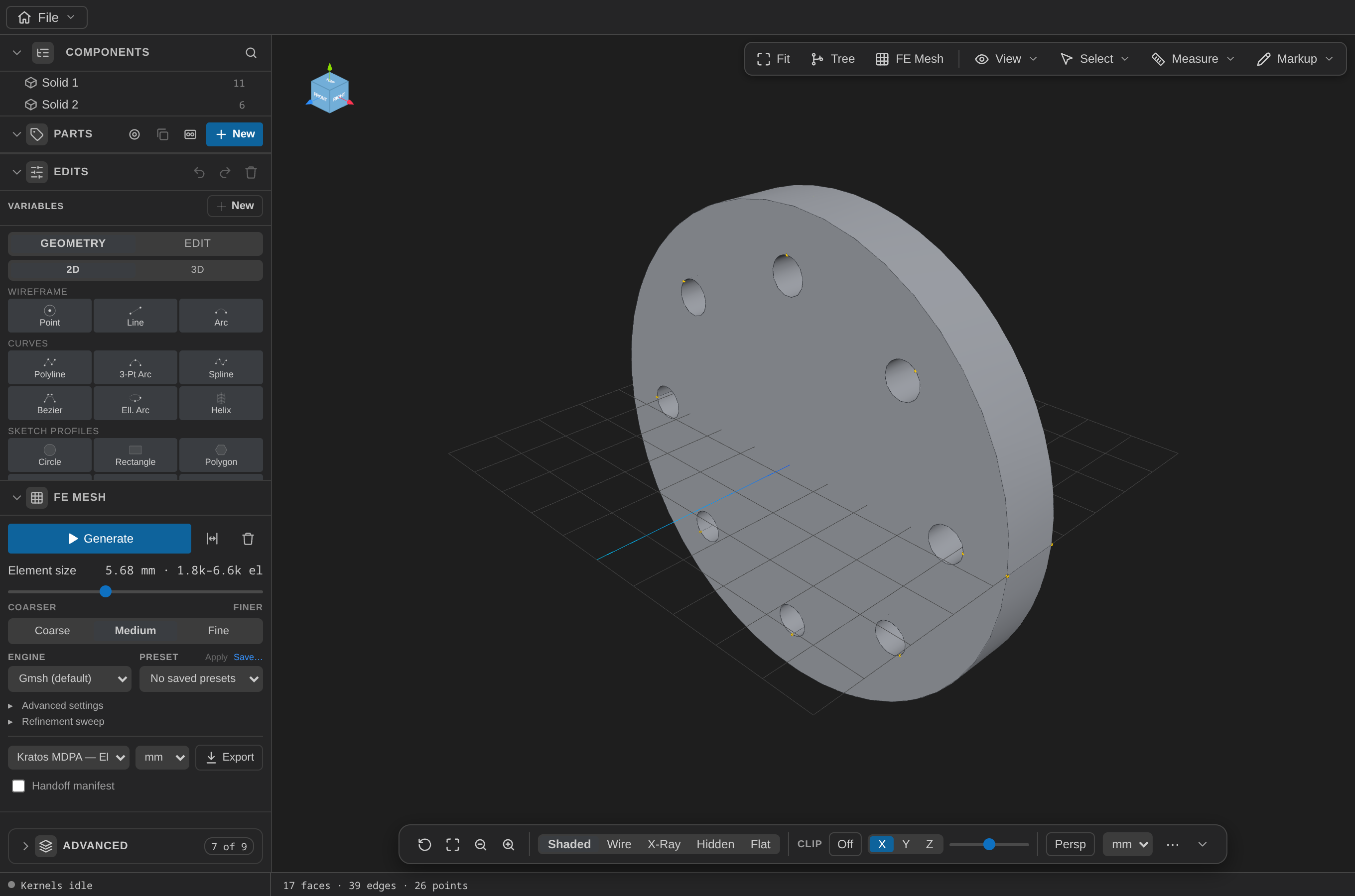
One subtract, eight holes. The flange keeps 3 faces of its own plus one cylindrical wall per hole — 11 in total.
Step 6 — Change your mind
Go back to the Variables table and set N to 12. The pattern re-evaluates and the flange re-drills.
You will need to widen the subtract's B list to match (solid-2 … solid-13) — the pattern knows about N, but the list of ids you hand the boolean is still a literal list. That asymmetry is the honest limit of the current op model: numbers are parametric, entity references are not.
Full operation list
Written as a run_parametric_script document, so the variables travel with the ops:
{
  "variables": [
    { "name": "R", "expr": "30" },
    { "name": "N", "expr": "8" }
  ],
  "steps": [
    { "op": { "op": "addCylinder", "center": [0, 0, -5], "axis": [0, 0, 1], "radius": 40, "height": 10 } },
    {
      "op": {
        "op": "addCylinder",
        "center": [30, 0, -10],
        "axis": [0, 0, 1],
        "radius": 3,
        "height": 20,
        "exprs": { "center[0]": "R" }
      }
    },
    {
      "op": {
        "op": "patternCircular",
        "targets": ["solid-2"],
        "axisPoint": [0, 0, 0],
        "axisDir": [0, 0, 1],
        "angleDeg": 45,
        "count": 8,
        "exprs": { "angleDeg": "360/N", "count": "N" }
      }
    },
    {
      "op": {
        "op": "boolean",
        "kind": "subtract",
        "a": ["solid-1"],
        "b": ["solid-2", "solid-3", "solid-4", "solid-5", "solid-6", "solid-7", "solid-8", "solid-9"]
      }
    }
  ]
}
The literal 45 and 8 sitting beside the exprs are the last computed values, not duplicates — every numeric field caches its most recent result so the model still opens correctly if a variable is ever deleted or fails to evaluate.
What you practiced
- Variables and expressions in place of literals, and the degrees convention for trig.
- Circular patterns, and that
countincludes the original. - Pattern-then-subtract — the standard way to array a cut feature when patterns only act on solids.
- The live-expression model: values re-resolve on read, and entity references stay literal.
Next: a shelled enclosure starts from a 2D sketch instead of a primitive.