Getting Started
This page is the reference: one section per panel, feature by feature. If you would rather learn by building something, the tutorials walk through a real part from start to finish and link back here for the details.
Installation
Install CAD Preview from the VS Code Marketplace:
- Open VS Code.
- Press
Ctrl+Shift+X(orCmd+Shift+Xon macOS) to open the Extensions view. - Search for CAD Preview by
kratos-multiphysics. - Click Install.
Alternatively, install from the command line:
code --install-extension kratos-multiphysics.cad-previewOr download and install the .vsix directly:
code --install-extension cad-preview-<version>.vsixSettings
CAD Preview contributes a few cross-document defaults under CAD Preview in VS Code's Settings UI (Ctrl+,, search "CAD Preview"). Most only affect newly opened documents — a document's own saved state (a .mesh.json sidecar's size, the toolbar Grid toggle for the current session) always wins once set. tessellationQuality is the one exception, re-read on every edit (see its own row below).
| Setting | Default | Effect |
|---|---|---|
cadPreview.background | #1e1e1e | 3D view background color (CSS hex) |
cadPreview.defaultMeshSizePreset | medium | Seeds the FE Mesh panel's target size (Coarse/Medium/Fine) for a model with no saved mesh options yet |
cadPreview.showGridAndAxesOnOpen | true | Show the ground grid and axes helper when a model is opened |
cadPreview.openscadBinary | openscad | OpenSCAD binary used to convert .scad sources to .csg on open (resolved via PATH when bare). Wins over the OPENSCAD_BINARY environment variable, the headless (MCP server) escape hatch. Unused when no .scad file is opened |
cadPreview.kernelTimeoutMinutes | 5 | Watchdog for a single kernel job (load, mesh, export…): a job running longer is killed and the kernel worker respawned. Applies to newly opened documents |
cadPreview.tessellationQuality | standard | B-rep (STEP/IGES/BREP/CSG/SCAD) tessellation density — draft/standard/fine; standard is identical to every previous version's fixed behavior. Unlike the other settings here, re-read on every edit, so a change applies to the next edit without reopening the file. Face triangle density only — does not affect edge display or the FE Mesh panel's own (separate) mesh generation |
cadPreview.upAxis | y | Default up-axis for newly opened models — set to z for Z-up source conventions |
Opening a File
CAD Preview activates automatically via the VS Code Custom Editor API. There is nothing to configure.
Open any supported file — for example, from the Explorer or via File > Open File…. VS Code routes it to the CAD Preview custom editor and the 3D view renders immediately.
You can also drag a file from the OS file explorer (or another editor tab) and drop it onto the 3D view to open it the same way. If the browser drop event doesn't expose a real filesystem path for the dropped item, CAD Preview falls back to showing the normal Open… dialog instead of silently failing.
The CAD Preview icon in the Activity Bar opens the Models view: every CAD/mesh file in the open workspace folder(s), discovered with the same routing rules (and the same depth cap and .git/node_modules exclusions) as the headless list_workspace_models tool. Click a file to open it in the 3D viewer; the toolbar offers Open…, Refresh, and New Blank Model… (new empty session — always visible, even when the workspace already has models). With no folder open — or no models found — the view shows Open CAD File… and New Blank Model… buttons instead.
Starting from Scratch
You don't need an existing file. File ▾ → New Blank Model… (also CAD Preview: New Blank Model… in the Command Palette, and the New button in the Models view toolbar) asks where to put a new .brep file, creates it empty, and opens it. From there the Edits panel's whole creation vocabulary is available — primitives (Box, Sphere, Cylinder, Cone, Torus, Prism, Wedge), 2D sketch profiles to extrude/revolve/sweep/loft, and bottom-up wireframe modeling (points → lines/arcs → Build → Surface → Build → Volume) — plus booleans, fillets, chamfers, patterns and everything else that works on a B-rep source.
Two things are worth knowing about how a blank model is stored:
- The
.brepfile itself stays empty until you explicitly save. Exactly as for an edited STEP file, your geometry is an ordered, replayable op-list in the<model>.brep.edits.jsonsidecar beside it; nothing writes the CAD file as a side effect of editing. Keep the pair together, or use Export… / Save Preprocess… to produce something standalone — or save in place (below) to bake the geometry into the.brepfile itself. - Export offers STEP/IGES and the mesh formats, plus the source's own format as a confirmed save-in-place — the export list excludes a document's own format only for the formats with no same-format writer (glTF, meshio++, CAD-text). Picking your own STEP/IGES/BREP/STL/OBJ/PLY writes the baked model back to the open file (with
.bak+ history watermark); export anything else for a file that carries the geometry itself.
New Blank Model only ever creates new files: if you point it at a path that already exists it refuses rather than overwriting, since blanking a model would leave its existing edit history replaying against nothing.
Supported Formats
| Format | Extensions | Rendering Pipeline |
|---|---|---|
| STEP | .step, .stp | OpenCascade.js tessellation |
| IGES | .iges, .igs | OpenCascade.js tessellation |
| BREP | .brep | OpenCascade.js tessellation |
| OpenSCAD CSG | .csg | CSG parse → OCCT build → tessellation |
| OpenSCAD Src | .scad | openscad binary → .csg → same as above |
| STL | .stl | Three.js STLLoader |
| OBJ | .obj | Three.js OBJLoader |
| PLY | .ply | Three.js PLYLoader |
| glTF / GLB | .gltf, .glb | Three.js GLTFLoader |
| VTK / VTU | .vtk, .vtu | meshio++ → STL boundary surface → Three.js |
| MED | .med | meshio++ → STL boundary surface → Three.js |
| CGNS | .cgns | meshio++ → STL boundary surface → Three.js |
| Exodus | .exo, .e | meshio++ → STL boundary surface → Three.js |
| XDMF | .xdmf | meshio++ → STL boundary surface → Three.js |
| Kratos MDPA | .mdpa | meshio++ → STL boundary surface → Three.js |
| OpenFOAM | .foam | meshio++ (case staging) → STL boundary surface → Three.js |
| Gmsh Mesh | .msh, .msh2 | meshio++ → STL boundary surface → Three.js |
| Abaqus | .inp | meshio++ → STL boundary surface → Three.js |
| I-DEAS Universal | .unv | meshio++ → STL boundary surface → Three.js |
| SU2 | .su2 | meshio++ → STL boundary surface → Three.js |
| INRIA Medit | .mesh | meshio++ → STL boundary surface → Three.js |
| GiD Postprocess | .post.msh (+ .post.res) | meshio++ → STL boundary surface → Three.js |
| Nastran Bulk Data | .bdf | routed, but current meshio++ reader rejects this extension's Gmsh-written deck |
B-rep vs mesh: STEP, IGES, and BREP are boundary-representation formats that are tessellated on-the-fly in the extension host. STL, OBJ, PLY, and glTF are already triangulated and are loaded directly into the webview by Three.js.
VTK/VTU/MED/CGNS/Exodus/XDMF/MDPA/OpenFOAM/Gmsh Mesh/Abaqus/I-DEAS Universal/SU2/INRIA Medit/GiD Postprocess have no native Three.js loader, so the extension host converts them to a triangulated boundary surface in STL form first (meshio++, entirely host-side — no browser involved) and hands that to the webview exactly like a native
.stlopen. This means Parts, Edits, Export, Mass Properties, and Measurement all work identically to STL. Named cell regions in the source file now auto-become real Parts on first import (one per region, pre-coloured and pre-assigned — for a tetrahedral/triangular boundary; a quad/hex boundary still doesn't correlate); scalar field data (temperatures, stresses, …) beyond region names is still not preserved — only its names are shown, not its values. If you need to inspect scalar field values or colour by them, keep using a dedicated viewer (e.g. ParaView) for those formats — CAD-Preview's support here is for quick geometry (and now region) previews alongside your CAD files, not full FE post-processing. Nastran.bdfis routed but remains incomplete: meshio++ rejects this extension's Gmsh-written deck even after header normalization; support is tracked in the roadmap.OpenFOAM (
.foam) is a case marker, not a mesh file. It's an (often empty) marker whose real mesh lives in sibling files under<parent>/constant/polyMesh/— CAD-Preview stages the whole case and hand-builds the boundary surface. OpenFOAM import is geometry-only: no patch names or field data are preserved (no Parts auto-create, no colour-by-field for it).Gmsh Mesh / Abaqus / I-DEAS Universal / SU2 / INRIA Medit close a real export/import asymmetry: the FE Mesh panel already wrote
.msh/.inp/.unv/.su2/.mesh, but until now had no way to re-open them..msh,.inpand.bdfare ambiguous extensions (also used by ANSYS/FreeFem, ANSYS APDL, and X11 bitmap fonts) — CAD-Preview shows a one-line status caveat on open; there's no automatic disambiguation into the alternate formats. Nastran.bdfimport remains incomplete: meshio++ rejects this extension's Gmsh-written deck even after header normalization. Known limitation: an.xdmfthis extension itself exports almost always fails to re-mesh after reimport, due to a separate, pre-existing meshio++ defect in reading back its own "mixed cell type" output — opening the file still works, only Generate on the reopened document doesn't.GiD Postprocess (
.post.msh) is a sibling pair, and unlike XDMF it re-meshes correctly after reimport. Geometry lives in the.post.msh, results in a.post.resbeside it that the reader finds by name convention — keep the two together; only the.post.mshis opened directly. It is both an import format and an FE Mesh panel export target.
User Interface
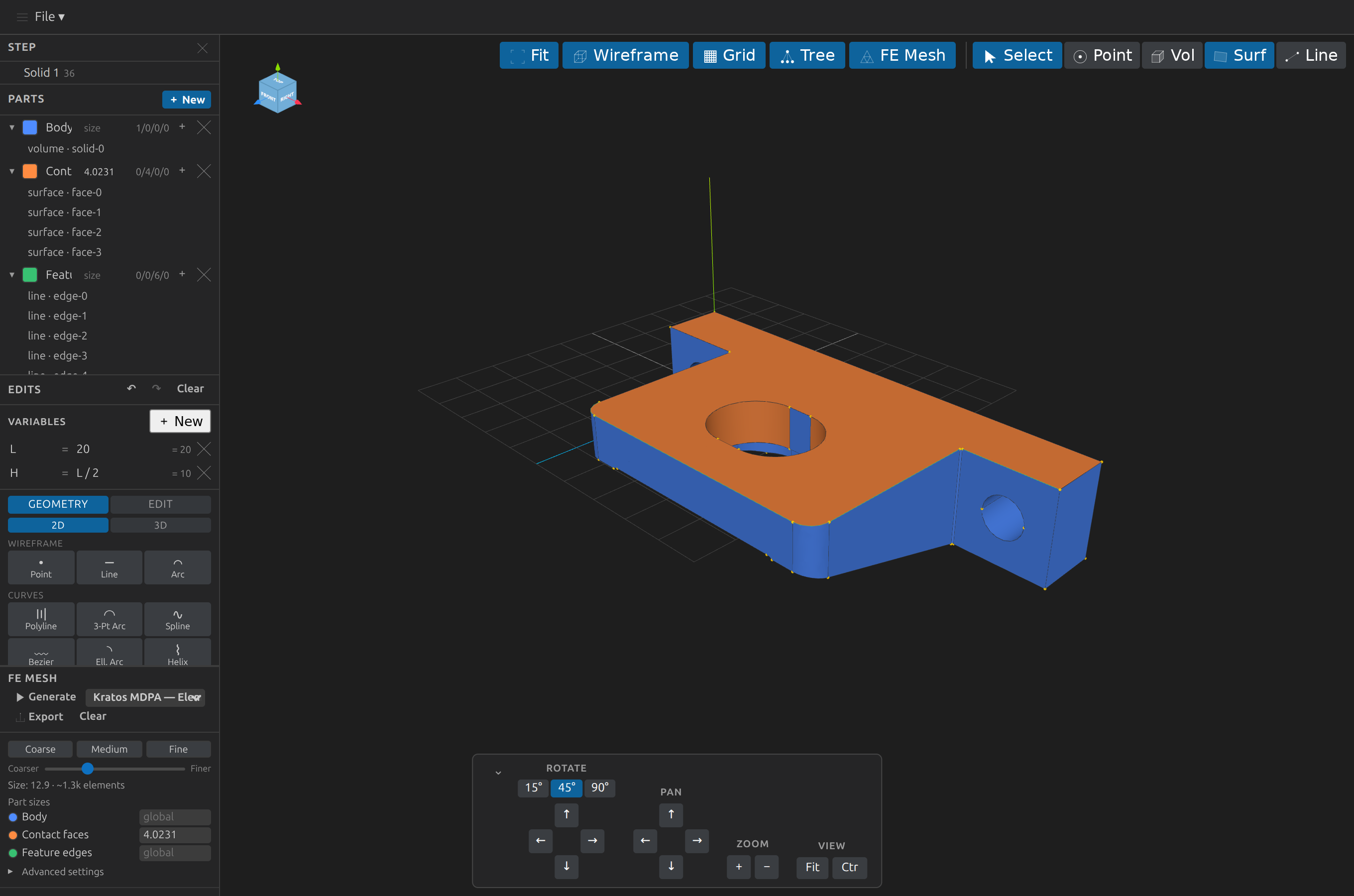
The full editor — here previewing bull.stp with three colour-coded parts assigned, parametric variables, and every panel populated.
Opening a STEP/IGES/BREP/CSG/SCAD file for the first time (or reopening one after an external change) shows a native VS Code progress notification with a Cancel button while OpenCascade parses and tessellates it. Clicking Cancel really stops the work — the toolbar status line immediately shows "Cancelled", this document's queued kernel jobs are dropped, and its running job is interrupted. It is scoped to this document: another open file's load or mesh is never interrupted by it, and closing a tab cancels only that tab's pending work. A subsequent edit or reopen starts a fresh load.
When a sidecar changes on disk while you have unsaved changes. Parts, edits, planes, annotations and mesh options autosave shortly after each change, and an external write (an agent's MCP call, a git checkout, another editor) is normally adopted automatically. If that external write lands while this editor still has a change waiting to autosave, neither version is dropped silently: a notification names the sidecar and both sides' counts, with Reload from disk (take the disk version) or Keep mine (overwrite). Dismissing it pauses that sidecar's autosave; File ▸ Save then overwrites the disk deliberately. If the CAD file itself is replaced while it has unsaved (unbaked) edits, you are asked whether to reload it rather than reloading silently. Routine edits (adding/undoing an operation) don't show this notification — with the model already parsed, they're normally near-instant and stay on the lightweight toolbar status line only.
The Advanced Group
Every section header reads chevron · icon · title, so a collapsed sidebar is still scannable by icon. The sidebar's top level holds only the four sections that edit the document — Components, Parts, Edits, FE Mesh. Everything that only reports on it, or pulls from a library, lives under a single collapsible Advanced group at the bottom:
| Advanced ▸ | Sections |
|---|---|
| Analysis | Mass Properties, Clash, B-rep Health, Mesh Health, Region fit, Primitives, Passages |
| Library | Macros, Standard Parts |
Advanced starts collapsed. Its header carries a badge counting how many of its nine sections apply to the current file (7 of 9 on a STEP source, where Mesh Health and Region fit want a mesh; a plain 9 when all of them apply), so you can tell whether opening it is worth the click without opening it. Each section inside keeps its own chevron and collapses independently, exactly as before — the group simply adds one more level.
Collapsing Sidebar Sections
Every sidebar section — and the Advanced group itself — has a chevron at the left of its header. Click it to collapse that section down to just its header, and again to expand it. Sections collapse independently, so you can reduce the sidebar to only what you're actually working with; collapsing the two flex-growing panels (Parts, Edits) hands their space back to the rest rather than leaving a gap.
The collapsed/expanded layout is remembered per document, in the same <model>.view.json sidecar that already stores the camera, display mode and clip plane, so reopening a file restores the sidebar exactly as you left it. Merely opening a document never creates that file — only an actual change does.
Sections that don't apply to the current file (Clash, B-rep Health, Primitives and Passages are shown only for a STEP/IGES/BREP source; Mesh Health and Region fit only for a native STL/OBJ/PLY/glTF source) are hidden entirely rather than collapsed, independently of this — the Advanced badge is what tells you how many were left out.
Resizing the Sidebar
Drag the thin handle at the sidebar's right edge (or hover/focus it — it highlights) to resize the whole column between a workspace-usable minimum and maximum. The handle is also keyboard-operable when focused: ArrowLeft/ArrowRight step the width, Home/End jump to the minimum/maximum. The chosen width is remembered per document in the same <model>.view.json sidecar (like the collapse state), with the pre-resizer 220px width treated as "default" — an unresized document never grows a sidebarWidth entry just from being opened.
The floating view-controls dock is centred over the 3D view and abreast of the sidebar, so resizing the sidebar never hides its controls; if the control row would be wider than the remaining canvas, it wraps onto a second row inside the dock rather than covering nearby panels.
Keyboard Use
The File ▾ / View ▾ / Select ▾ / Measure ▾ / Markup ▾ dropdowns are keyboard-reachable end to end: Tab from the main canvas reaches the toolbar triggers; opening a menu and pressing ArrowDown/ArrowUp cycles its buttons (wrapping), Home/End jump to the first/last item, and Escape closes the menu and returns focus to its trigger. Icon-only buttons (Fit, Tree, the per-row eye/delete buttons, the collapse chevrons) are screen-reader labelled; their aria-label always mirrors the visible tooltip. Inline renames — Parts, Variables, construction planes — commit on Enter (or on clicking away) and cancel on Escape, leaving the value they had when the edit began.
Camera Interaction
| Action | Control |
|---|---|
| Orbit | Left-click drag |
| Pan | Right-click drag |
| Zoom | Scroll wheel |
Camera movement uses Three.js OrbitControls with damping enabled for smooth deceleration.
File Menu
A full-width menu bar sits at the very top of the editor with a single File ▾ dropdown:
| Item | Action | Shortcut |
|---|---|---|
| New Blank Model… | Start an empty model and build it from scratch with the Edits panel — see Starting from Scratch | — |
| Open… | Pick another CAD/mesh file and open it in CAD Preview | Ctrl+O |
| Save | Immediately flush the parts/annotations/edits/mesh sidecars (.parts.json / .annotations.json / .edits.json / .mesh.json). The sidecars also autosave on a ~500 ms debounce, so this just forces an immediate write — the CAD source itself is untouched (use Ctrl+S / the dirty dot to bake the op tail into the file). | — |
| Save As… | Convert the model to a new file/format via the Export flow | Ctrl+Shift+S |
| Export… | Convert the model to a compatible format and save it — or pick the source's own format to save the edits back into the open file itself (confirmed, with a .bak backup) — see Exporting a Model | Ctrl+E |
| Save Preprocess… | Bundle the CAD file plus whichever of its .parts.json / .annotations.json / .edits.json / .mesh.json sidecars currently exist into a single .zip archive (with a per-entry SHA-256 checksum recorded in its manifest), so the whole working state can be shared or archived as one file | Ctrl+Alt+S |
| Load Preprocess… | Restore a .zip built by Save Preprocess: pick a destination for the CAD file, write back whichever sidecars it contains, and open the result — rejects a corrupted/tampered archive or a destination whose file extension doesn't match the archive's own format | Ctrl+Alt+O |
| Import SVG… | Pick a .svg file and import every <path>/<rect>/<circle>/<ellipse>/<line>/<polyline>/<polygon> in it as sketch Polyline edit ops — one per closed/open subpath (a shape with a hole, e.g. a traced letter "O", becomes two separate polylines) — with every ancestor's transform composed in, so a real "convert text to outlines" export (typically wrapped in one or more <g transform="..."> groups) imports at the right place and scale. Build → Surface then accepts an outer loop's edges together with its hole's to build a single holed face in one step, ready to Extrude/wrap onto a cylinder. B-rep only; <use> and <text> are recognized and reported in the status line rather than silently skipped (<text> needs converting to outlines first) | — |
| Import DXF… | Pick a .dxf file and import its model-space LINE / LWPOLYLINE (bulge arcs sampled) / POLYLINE / CIRCLE / ARC / SPLINE entities as the matching Line/Polyline/Circle/Arc/Spline edit ops. B-rep only; blocks/INSERT/TEXT/DIMENSION/HATCH and paper space are skipped, and geometry lands flat at z=0 (1 DXF unit = 1 mm, Y-up native — adjust afterward with Scale/Move/Rotate) | — |
| Export Silhouette SVG… | Write a 2D outline of the model as an .svg file — pick a view (Current view, or Front/Back/Top/Bottom/Left/Right/Iso), then an export unit, then a destination. An outline, not a dimensioned technical drawing (see Exporting a Silhouette SVG) | — |
| Export Silhouette DXF… | The same outline flow with a DXF serializer (LWPOLYLINE chains + LINE singletons), saved with a .dxf extension | — |
| Export Technical Drawing… | A 2D drawing with hidden-line removal: feature edges solid where visible, dashed where hidden behind the part. Unlike the two silhouette exports it draws interior edges too, so a hole's far rim shows dashed. Same view and unit picks; SVG or DXF (where hidden geometry lands on a HIDDEN layer). Still a review artifact and a single view — pinned annotations still bake in as dimensions | — |
| Export Drawing Sheet… | Several views (front/top/right/iso by default) on one sheet at a shared scale, orthographically aligned (first-angle by default) with a title block. Format, then paper size, then export unit, then a destination. A pinned annotation is drawn once, in whichever view shows it at true length (see Exporting a Drawing Sheet) | — |
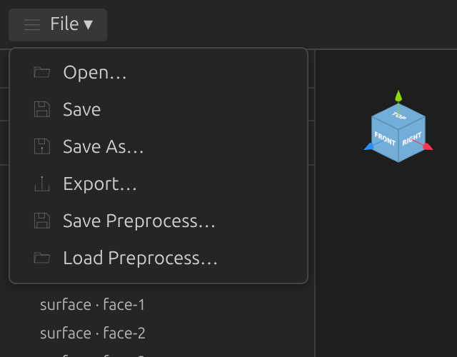
Every item is also a VS Code command (CAD Preview: … in the Command Palette). The keyboard shortcuts are scoped to a focused CAD Preview tab, so they don't override VS Code's global Open/Save elsewhere.
What's New
The first time you open a CAD file (or run any CAD Preview: … command) after an update, a What's New tab opens beside the editor summarizing everything that changed since the version you last had installed — just close it (or click Got it) and keep working. It won't show again until the next update. You can reopen it anytime via CAD Preview: Show What's New in the Command Palette, which shows the full changelog rather than only what's new since your last session.
Toolbar
The toolbar appears at the top-right of the editor, just below the menu bar. Three always-visible buttons sit on the left; everything else is grouped behind four dropdown menus, so the strip stays compact:

| Button | Action |
|---|---|
| Fit | Reframe the model to fill the viewport (keeps current camera orientation) |
| Tree | Show/hide the component tree panel (visible only for models with multiple components) |
| FE Mesh | Toggle the generated finite-element mesh overlay on/off (see Generating an FE Mesh). The FE Mesh panel itself is always visible in the sidebar; this button only shows/clears the overlay. |
A dropdown closes when you click its trigger again, press Escape, or click anywhere outside it; opening one closes any other that was open. Clicks inside a panel leave it open, so you can flip a mode on, pick a tool, and choose a colour in one visit. When the mode behind a menu is active, its trigger stays highlighted with a small dot, so you can tell at a glance that Measure or Markup is still live after the panel has closed.
View ▾
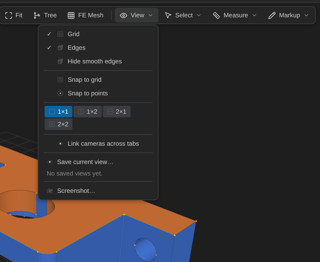
| Item | Action |
|---|---|
| Grid | Show/hide the world-space grid and axis helpers (ticked when shown) |
| Edges | Show/hide edge lines independently of the shaded faces (ticked when shown) |
| Hide smooth edges | Declutter tangent patch-seam edges (e.g. between adjacent NURBS patches of one conceptually-curved surface on an imported STEP file) while keeping genuine feature edges — ticked when smooth edges are hidden. Off by default, so an existing model looks unchanged until you opt in |
| Snap to grid | While dragging the Transform Gizmo in Translate mode, round the move to whole multiples of the Grid size field (view-controls Appearance group, default 1) — off by default |
| Snap to points | While dragging the gizmo, snap a moved solid's nearest corner onto a nearby existing point-N vertex (any B-rep vertex or standalone point in the model) once it's within about 1% of the model's size — off by default. Both toggles can be on together; grid-snap applies once to the whole dragged group, point-snap then applies per solid, so different solids may snap to different nearby points |
| Pane layout | Four mutually-exclusive layouts over the same scene — 1×1 (single view), 1×2 (two side-by-side columns), 2×1 (two stacked rows), 2×2 (quad) — each pane an independent camera (direction/up/ortho) over the single WebGL canvas; display mode, clip plane, selection, parts colours, overlays, and markup stay shared across all panes. Orbit, pan, zoom, the Persp/Ortho toggle, and the orientation cube all work per pane, and clicking a pane makes it the one the view-control buttons act on. All panes of a new layout start as copies of the current view; collapsing keeps whichever pane you were last in. Persisted to <model>.view.json alongside camera direction (reopens exactly as you left it, including the per-pane cameras — older sidecars without a layout still restore sensibly to single-pane) |
| Link cameras across tabs | Share the focused pane's camera (direction/up/ortho) across all open CAD Preview tabs — orbiting one tab's view mirrors in the others within ~500 ms, re-framed to each document's own extents. Provider-level on/off (one checkbox for all tabs), session-only, never written to .view.json |
| Save current view… | Save the current camera, display mode, and clip plane as a named view bookmark — a per-document collection of inspection viewpoints persisted to <model>.view.json. Each saved row restores on click (into the focused pane, re-framed to the model's current extents, so it stays meaningful after edits change the model's size), and offers Replace (overwrite with the current view), Rename (inline, Enter commits / Escape cancels), and ✕ Delete. Restoring also becomes the persisted latest view, so reopening shows what was last on screen |
| Screenshot… | Save the current 3D view as a PNG via a Save dialog (see Taking a Screenshot) — in a split view this captures the whole quad |
Select ▾
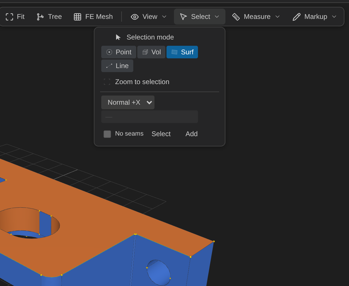
Selection mode toggles entity picking; the Point · Vol · Surf · Line row chooses what a click picks — points (vertices), volumes (solids), surfaces (faces), or lines (edges). Used to assign geometry to parts (see Defining Parts) and to feed the wireframe Build composer (see Editing Geometry). Pick modes a given file format can't offer are greyed out. Zoom to selection frames the current selection in the focused pane (keeping its orientation, in perspective or ortho — explicit Fit still frames the whole model); an empty or hidden/stale selection explains itself on the status line instead. Also available as CAD Preview: Zoom to Selection from the Command Palette. A filter form below the row lets you select by shape instead of by clicking: faces — Normal ±X/±Y/±Z, Planar, Area ≥/≤, Largest/Smallest N; lines — Along X/Y/Z, Length ≥/≤, Longest/Shortest N — plus a No seams toggle that skips tangent seam edges; volumes — Size ≥/≤ (bbox diagonal), Center ±X/±Y/±Z (bbox-center coordinate), Largest/Smallest N (by bbox volume); points — Near XY/XZ/YZ (distance to the coordinate plane), Near selection ≤ and In selection box × (measured against the current selection's centroid — select something first). All thresholds are in model millimetres, like the geometry itself. Select replaces the current selection; Add unions into it.
Measure ▾
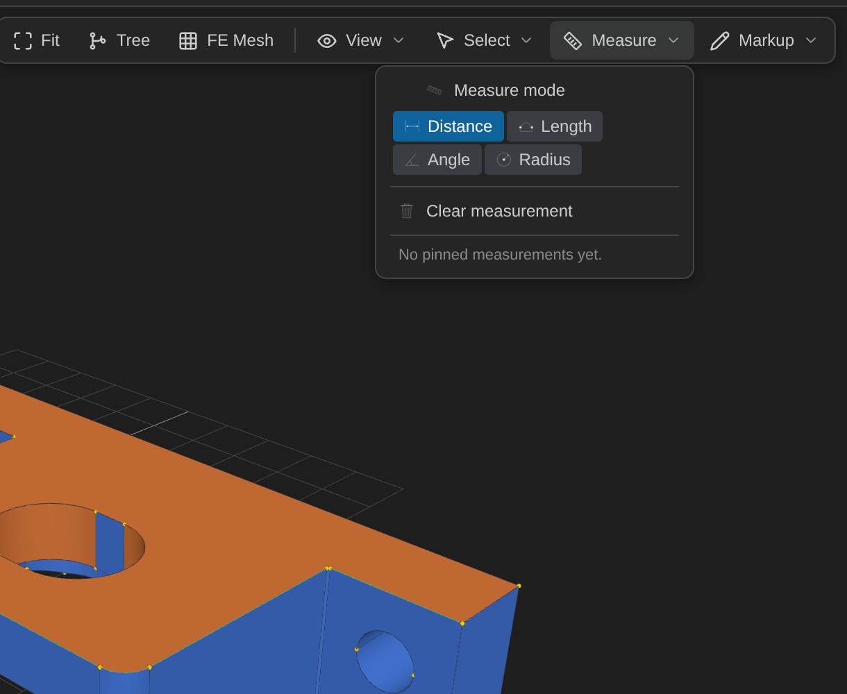
Measure mode toggles measurement picking; the tool row selects Distance, Length, Angle, or Radius, and Clear measurement discards the current one (see Measuring). The result appears on its own line just below the toolbar, so it stays readable with the menu closed. A Saved list at the bottom of the panel shows any pinned annotations (📌, see Pinning a measurement below).
Markup ▾
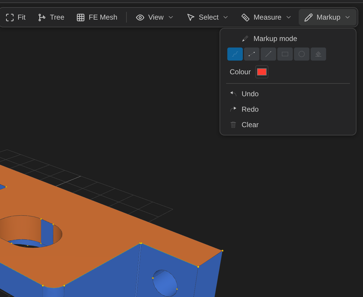
Markup mode toggles annotation drawing; the tool row selects Freehand, Line, Arrow, Rectangle, Circle, or Eraser, the swatch sets the stroke colour, and Undo / Redo / Clear manage the strokes (see Markup Annotations).
Taking a Screenshot
Click View ▾ → Screenshot… in the toolbar (or run CAD Preview: Screenshot to PNG… from the Command Palette, Ctrl+Alt+P) to save the current 3D view — whatever orientation, display mode, mesh overlay, and markup annotations are currently shown — as a PNG. A native Save dialog defaults to the source file's folder.
Markup Annotations
Open Markup ▾ in the toolbar and click Markup mode to start drawing review notes directly over the 3D view — "this boss", "gap here" — without leaving the viewer. Pick a tool from the row below it (Freehand, Line, Arrow, Rectangle, Circle, or Eraser) and a stroke colour from the swatch, then click-drag on the view to draw. Undo/Redo step through your strokes one at a time; Clear removes them all. Annotations are session-only — never saved to any sidecar or the CAD file — but they ARE baked into the next Screenshot you take (see above), so you can mark up a view and export the annotated image in one flow. Loading a different model clears any existing annotations; switching display mode, applying an edit, or rotating/panning the view does not. Erasing a stroke with the Eraser tool is immediate and does not go through Undo/Redo. Toggle Markup mode off to resume orbiting/panning/picking normally — while it is active, clicks draw instead of orbiting the camera. The Markup ▾ trigger stays highlighted while the mode is on, even after the menu closes.
The View-Controls Dock
The floating dock at the bottom of the 3D view holds the controls you reach for while orbiting. It is one compact row with a ⋯ button at its right end that opens a popover for the controls used less often. (The counts, mesh stats and cursor position that used to sit under it moved to the full-width status bar along the bottom of the window.)
| Where | Controls |
|---|---|
| In the row | Icon navigation — reset view, fit, zoom out, zoom in — then the Display modes (Shaded / Wire / X-Ray / Hidden / Flat, as text segments), the Clip plane (its on/off toggle, then X / Y / Z and the offset slider), Persp / Ortho, and the Units dropdown. A small chevron at the very end of the bar collapses the whole dock |
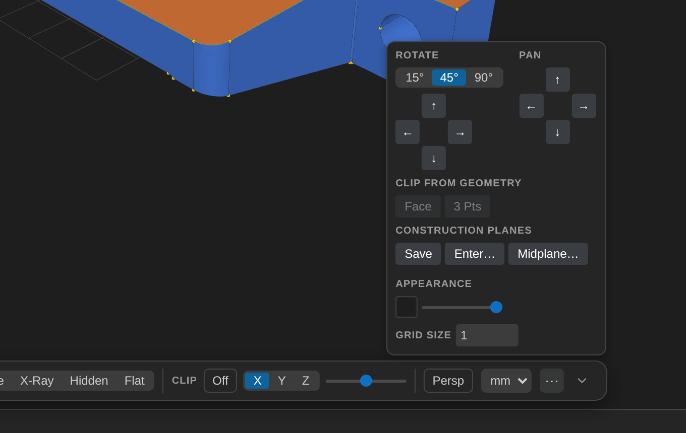
| Behind ⋯ | Rotate and Pan arrow pads, clip Face / 3 Pts, the Planes group, background colour, opacity, Grid size, and Colour by field (shown only for a meshio++ source that declares one) |
Nothing was removed — every control that used to sit in the tall two-tier panel is still one click away. The popover opens upward, stays on the canvas rather than covering the sidebar, closes on Escape or an outside click, and is arrow-key navigable like the toolbar menus. On a narrow editor the row wraps onto a second line instead of overflowing.
Colours follow your VS Code theme. The dock, toolbar, chip and status bar use the theme's own colours (light, dark, and high-contrast all work); only the model's own colours — background, faces, edges — come from the separate scene palette.
The panel's remaining controls in detail:
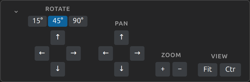
Rotate buttons — Step the camera by 15°, 45°, or 90° around the azimuth or elevation.
Pan buttons — Shift the camera target by a fraction of the viewport.
Zoom buttons (magnifier − / +) — Dolly in or out by a fixed factor.
Fit (frame icon) — Same as the toolbar Fit button (reframe in current orientation).
Reset (circular-arrow icon) — Reset to the default isometric view
(1, 0.8, 1)and reframe.Clip group — Enable a live section/clipping plane, then drag the offset slider to sweep it across the model's bounding box (
-1= the min-side face,0= centre,1= the max side), measured along whichever normal is active. The cross-section is solid-filled, not see-through, and also applies to the FE Mesh overlay when shown. Turning it off instantly restores the full model.The plane can be any direction, not just an axis:
- X / Y / Z are fast presets.
- Face clips along a selected planar face — select exactly one face in Surf mode and click it. The plane is oriented so the model is kept rather than cut away entirely, so for a face on the outside of the part nothing is cut until you drag the slider, which then sweeps inward from that face. Picking a curved face reports which surface type it found instead of applying a meaningless plane. B-rep sources only.
- 3 Pts clips through three selected points — select exactly three in Point mode. The result doesn't depend on the order you clicked them. Three points in a straight line are rejected with an explanation.
Once a custom normal exists, a fourth N segment appears beside X/Y/Z showing it (hover for the vector and where it came from). It stays selectable, so you can flip to an axis preset to look at something and flip straight back without re-picking. The custom normal is saved to
<model>.view.jsonalong with everything else in the panel.Planes group — Named construction planes, saved beside the model in
<model>.planes.jsonso they survive closing the file. Save clip stores whatever the Clip group is currently showing; Enter… reveals fields for typing a point and a normal directly, which is the only way to author a plane with no geometry to pick; Midplane… reveals two dropdowns of the already-saved planes and adds a new plane halfway between the picked pair (their normals must be parallel). Each row offers Use (apply it as the clip — the same path the Face/3 Pts buttons take, so a saved plane behaves identically to a freshly derived one), rename, and delete. Hover a row for its point, normal, and where it came from.A plane stays put. It stores the actual vectors, not a reference to the face it came from, so an edit that renumbers face ids leaves it exactly where you saved it — unlike Part and annotation assignments, which are re-matched geometrically. See Construction Planes Sidecar.
Appearance group — A background-colour swatch (live preview only — the session-only override always wins over the
cadPreview.backgroundsetting until you reload), an opacity slider for the whole model, a Persp / Ortho button toggling between perspective and orthographic projection (orbit/pan/zoom, picking, and the orientation cube all keep working under either projection), a Units dropdown (mm/cm/m/in/ft, see Units below), and a Grid size field controlling the Transform Gizmo's Snap to grid increment (see View ▾ above — unrelated to the display grid's own Grid toggle). For a meshio++-imported source that declares point or cell scalar data (temperatures, stresses, …), a Colour by field dropdown also appears here — picking a field paints the model as a viridis colour ramp with a min/max legend; picking "None" reverts. Background/opacity/units/grid-size/colour-by-field stay session-only (never exported/persisted); colour-by-field additionally resets whenever an edit is applied, since a field's values only stay meaningful for the model's original, unedited geometry.Display group — Five mutually exclusive rendering modes, replacing the old standalone Wireframe toolbar toggle: Shaded (the default, lit faces), Wire (faces rendered as a mesh of lines), X-Ray (translucent faces so edges show through), Hidden (edges of occluded geometry shown faintly through solid faces, full-strength where actually visible), and Flat (unlit, constant-colour faces — no lighting gradient, useful for reading true part colours without shading artifacts).
The camera direction/up vector, Persp/Ortho, Display mode, and the Clip plane are all saved automatically to a <model>.view.json sidecar and restored the next time you open the same file, so reopening a large assembly picks up right where you left off instead of always resetting to the default isometric — see View State Sidecar for the format. Applying an edit reframes in your CURRENT direction rather than snapping back to the saved (or default) one. Background colour, opacity, the Units dropdown, and Colour by field remain purely session-only, as does explode-preview state (the committed explode op itself is saved in .edits.json like any other edit).
The Document Chip and Status Bar
Two small readouts report facts about the open document without asking you to do anything:
- Document chip — at the right end of the menu bar: the file name, a small format badge (
STEP,STL, …), and — when the document has unsaved edits, meaning an edit-op tail that a save would bake into the source file — a dot and the count (3 unsaved edits). It reads the same rule the editor tab's own dirty dot does, so the two agree while you edit and save; hover the chip for the full path. Two moments where it can differ from the tab, both intentional: on opening a file whose sidecar already holds edits that haven't been saved into the source, the chip shows the dot straight away (the tab stays clean until you change something), and after undoing back to the save point the chip's dot clears while the tab's dot stays until you save or revert (VS Code has no way to un-dirty a tab from an undo). - Status bar — the full-width strip along the bottom of the window. At its left, under the sidebar, kernel readiness (
OCCT ready · Gmsh ready): which of the WebAssembly kernels (OCCT, Gmsh, meshio++, fTetWild) this session has actually used. They load lazily on first use, so a document that never needs one — a plain STL open, for instance — honestly readsKernels idle; a kernel shows ready only after a call that needed it has succeeded, and goes back to idle if the worker is cancelled or restarts. To the right of that: entity counts for a B-rep document (36 faces · 98 edges · 64 points, the entities you can pick), the FE-mesh stats once you generate one (mesh 51,200 el · min SICN 0.412— hover it for the node count too; the full quality histogram stays in the FE Mesh panel), and the live cursor position (x 142.06 y -18.40 z 27.00 mm) in the model's own frame, following the Units dropdown. The position appears while the pointer is over the model and clears when it leaves; it works whether or not selection mode is on. Counts are shown for B-rep documents only — a mesh file has no comparable count that wouldn't change with how its facets are split — and there is deliberately no solid count, since sketch faces would make it off by one.
Explaining the geometry under the cursor
With a pick mode active (Select ▾), two things explain what you are pointing at.
Hovering shows a small tooltip with the entity's id (face-12, edge-3, solid-0) and which of your applied ops mention that id. This is the quickest way to read your own .edits.json: the ids in the sidecar are exactly the ids under your cursor. It says mentions, not acts on, deliberately — ids are positional, so the same face-12 in two different ops can refer to different geometry once an op in between renumbers things.
Clicking additionally opens an inspector card in the top-right corner of the view, classifying the entity analytically: a planar / cylindrical / conical / spherical / toroidal face, or a straight / circular / elliptical / spline edge. It lists only the measurements that classification gives meaning to — a plane gets its area, normal, and a point on its plane; a cylinder gets no normal at all, because a curved face has no single one.
The card needs the CAD kernel, so it is B-rep only (STEP/IGES/BREP/CSG/SCAD) and appears on selection rather than on hover — a triangle mesh has no analytic surface type to report, and a fine-faceted prism is indistinguishable from a cylinder in triangles.
Right-clicking an entity offers computed selection groups with their member counts — "Same facing (3)", "Planar faces (19)", "Area ≤ this (36)" for a face; "Parallel to this", "Length ≥/≤ this" for an edge. Hovering a row previews exactly what choosing it would select; clicking replaces the selection, and shift-clicking adds to it.
These are the same predicates as the Select ▾ panel's filter form, with one difference that makes them worth reaching for: the entity you right-clicked supplies the number. "Area ≤ this" is the filter form's Area ≤ with the threshold already filled in. Groups are offered for Surf and Line modes only — the same modes the filter form supports — and a group that would select only the entity you clicked is not offered at all.
The menu's first row, Pin note…, works in every pick mode: it turns the menu into a text field; type a note and press Enter to pin it to the entity you right-clicked, at the point you clicked (Escape cancels). A note is a saved annotation like a pinned measurement: it lists in the Measure ▾ Saved list as Note: …, survives reopening the file, follows its entity across edits, is baked into SVG/DXF drawing exports as a label, and is the same record the pin_annotation MCP tool writes with tool: "note".
Macros
The Macros sidebar panel saves a set of edits you have already applied as a named, reusable script, so a bolt pattern or a standard bracket treatment does not have to be rebuilt by hand every time.
Save current records the current edit history under a name you choose; the document's own parametric variables come along as the macro's parameters. Each saved macro then lists those parameters with an editable field seeded from its saved default — change one and press Run to apply the macro at the new values.
Running a macro pushes its ops onto the ordinary edit history, so it is undoable, visible in the history list, and removable op-by-op exactly like a hand-applied edit — there is no separate "macro" state to reason about.
Macros live in cad-preview-macros.json in the model's own folder, shared by every model there. That is the same file the MCP tools read and write, so a macro you record by hand is directly runnable by an agent and vice versa.
Three starter macros ship with the extension and are listed above your own entries — spring (a helical spring: wire-radius circle swept along a helix, parameters R/W/P/N), bolt-circle-flange (the bolt-circle flange walkthrough as a runnable macro, parameters R/N), and hex-bolt (hex-prism head fused to a shaft, parameters headR/headH/shaftR/shaftL). They run like any macro but show no Delete button (read-only). All three assume a blank model (File ▸ New Blank Model) — their sweep/pattern/boolean steps reference the entity ids those steps create on an empty base.
Theme
The 3D scene follows VS Code's active colour theme. Switching between a light, dark, or high-contrast theme repaints the background, the default face/edge/point colours, the grid, the scene lighting, and the FE mesh overlay immediately — no reload, and nothing is written to any sidecar.
Colours you chose yourself are never re-tinted. A Part's colour swatch, and a per-part FE mesh colour, are your data: they win over the themed default, so a theme switch leaves them exactly as you set them. The same applies to a background you picked by hand in the Appearance group — once you drag that swatch, your choice wins for the rest of the session.
Two things deliberately do not follow the theme: the orientation cube's red/green/blue axis arrows (an axis-colour convention shared across CAD tools, not a theme detail), and a live operation preview's intent tint, which is regenerated whenever the draft changes anyway.
Units
CAD Preview always keeps geometry internally in one consistent unit (millimetres) — for STEP files this is automatic: the OCCT reader converts every shape to millimetres at load time regardless of what unit the file was authored in (inches, centimetres, …), so numbers are always consistent no matter the source. The Units dropdown in the view-controls Appearance group is purely a display preference on top of that: it rescales how Mass Properties and Measurement results are shown (with a unit suffix, e.g. 12.700 mm or 0.500 in) — nothing stored (edit-op parameters, sidecars, mesh-size options) is ever rescaled, and FE Mesh panel size fields always show plain millimetres regardless of this setting, since that's Gmsh's own working unit. Opening a STEP file whose DATA section declares a length unit (e.g. INCH), or an IGES file whose Global section declares one (its own, differently-structured way of recording a unit), seeds the dropdown to that unit automatically; opening a file with no declared/recognized unit, or a mesh format (which has no unit metadata at all), always starts from mm. Moments of inertia in the Mass Properties panel are intentionally never rescaled by this setting. The selection is session-only — it resets on every new file open and is never written to a sidecar.
This dropdown is unrelated to (and doesn't drive) the Export flow's own unit conversion — see Exporting a Model, which applies a real geometric scale to the exported file, not just a display change.
Orientation Cube
A labeled orientation cube sits in the top-left corner of the 3D view. It mirrors the current camera direction in real time.
Click any face of the cube to snap the camera to that standard view:
| Face | View |
|---|---|
| +X / -X | Right / Left |
| +Y / -Y | Top / Bottom |
| +Z / -Z | Front / Back |
Component Tree Panel
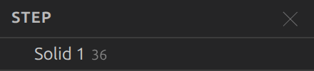
For multi-solid STEP/IGES assemblies or glTF scenes with multiple meshes, the component tree panel shows the model hierarchy. Click any row to highlight that solid/mesh in the 3D view (all others are dimmed). Click the same row again or click an empty area to deselect.
For STEP sources specifically, the tree reflects the file's own real assembly structure when it has one — nested "Assembly"/"Component" groups matching how the file's author organized it, instead of always flattening every solid into one list (product/component names aren't shown — they're unreadable in this build's OCCT WASM — and an assembly wrapper with no real internal structure, or a source with none at all, falls back to the flat list exactly as before). A group-header row (an "Assembly N" line) is informational only — clicking it or its eye-toggle has no effect; only a leaf ("Solid N") row highlights/hides, exactly like every row always has.
Click the search icon in the Components header to reveal a filter field and narrow the list to rows whose name matches (case-insensitive substring) — matching rows and their ancestors stay visible so a match is never hidden inside a collapsed-looking branch. Escape (or the search icon again) closes the field and clears the filter, so a hidden box never keeps hiding rows. The section stays titled Components (the source format is on the document chip). Rows show a cube for an assembly group and a box for a solid; a solid's right-hand number is its face count and an assembly's is how many solids it holds (hover either for which). Each row also has an eye-toggle, shown when you hover or focus the row (and always while something is hidden), to hide/show that solid/mesh (and its edges/points) in the 3D view — a display-only toggle, same as the Parts panel's (see below), never saved to a sidecar.
Measuring
The Measure ▾ toolbar menu lets you measure distances, edge lengths, angles, and circle/arc radii directly in the 3D view — display-only by default, and never an edit operation, but a result can optionally be pinned so it survives closing the file (see below).
- Open Measure ▾ and click Measure mode (orbit/pan/zoom still work normally — a measurement pick is a click without a drag, same as part selection).
- Pick a tool from the dropdown: Distance and Angle need two picks; Edge Length and Radius resolve from a single click.
- Click in the view. Distance: click two points anywhere on the model. Edge Length: click one edge. Angle: click two faces or edges. Radius: click one circular/arc edge. A line (for Distance/Angle) plus a floating label with the result appears, and stays readable while you zoom.
- Click Clear to remove the current result, or switch tools/toggle Measure off to start over.
Measurement precision follows the model's tessellation (the same 0.1 deflection tolerance used for display), not exact CAD geometry — fine for visual estimates, not for metrology-grade output. Distance, Edge Length, and Radius results are shown in whatever unit the view-controls Units dropdown is set to (see Units above); Angle is always degrees.
For a STEP/IGES/BREP model, a ⟟ Exact button appears next to a completed Distance, Edge Length, or Radius result (not Angle — there's no exact counterpart for that one). Clicking it asks the extension host to recompute the same measurement against the true OCCT geometry instead of the displayed triangulation — the readout updates to D_exact/L_exact/R_exact = … once it comes back. This is a real (if fast) computation, not instant like the triangulated result, and only works for CAD sources — mesh formats (STL, OBJ, …) have no exact B-rep geometry to fall back to, so the button never appears for them.
Pinning a measurement
A 📌 Pin button appears next to a completed measurement result on any source kind (unlike ⟟ Exact, which is B-rep only). Beside it sit three small optional tolerance fields — nom, +, and −. Fill at least nom and + (leave − blank for a symmetric ± band) and the pinned annotation records that tolerance band alongside the measured value; pinning with only nom filled still pins, but tells you no band was recorded. Clicking Pin saves the result as a persisted annotation — a "Saved" list at the bottom of the Measure ▾ panel shows every pinned measurement, with a Show action (re-displays that overlay, no recompute) and a ✕ to delete it. Annotations survive closing the file, saved to a <model>.annotations.json sidecar next to the CAD source (the CAD file itself is still never touched).
A completed 2-point measurement (Distance or Angle) now renders as an actual dimension: arrowheads at both measured points, short witness marks, and the value label — not just a bare line. A toleranced pin shows its band in the label (12.5 mm [10 ±0.05]), and if the frozen measurement falls outside its own band, both the re-displayed label frame and its Saved-list row are coloured red — a presentation choice derived from the stored facts; nothing stores a pass/fail verdict. Pinned annotations also appear as dimension glyphs (extension lines, arrowheads, value labels) in File ▾ → Export Silhouette SVG/DXF… drawings.
Unlike Markup strokes (screen-space pixels with no 3D anchoring at all), a pinned annotation stays attached to the actual entity it measured — a geometric best-effort match runs automatically whenever you apply a topology-changing edit elsewhere on the model, the same matching that already keeps Parts assigned correctly across edits. If the specific entity an annotation anchored to is later removed or fused away (a boolean, for example), the annotation degrades honestly: its row in the Saved list goes struck-through and Show disables, rather than silently pointing at the wrong geometry.
Defining Parts
CAD Preview lets you group geometry into named parts (the FEM sub-model-part / boundary-group concept). The Parts panel sits below the component tree in the left sidebar.
To assign geometry to a part:
- Open Select ▾ in the toolbar, click Selection mode, and choose a pick target: Vol (solids), Surf (faces), or Line (edges).
- Click entities in the 3D view to select them — they highlight blue. Shift-click to add or remove from the selection; a plain click selects just one; clicking empty space clears the selection.
- Click + New in the Parts panel to create a part, then click the + on that part's row to assign the current selection to it.
Each part is a compact row: a colour swatch (click to recolour), an editable name, a 1 · 0 · 0 count of its volumes · surfaces · lines (a fourth number appears only if it has points), and an eye-toggle to hide/show just that part's entities. The + (assign the current selection) and delete buttons appear when you hover the row or focus into it. Assigned entities are painted in the part's colour in the 3D view. Click the chevron to expand a part (entity lists start collapsed) and remove individual entities; click a part row to highlight all of its entities. A part's target mesh size is edited in the FE Mesh panel's Part sizes section.
The panel header's Isolate button (target icon) shows only the currently-selected part's entities, hiding everything else; click it again (or select a different part and click it again) to clear isolation. Isolating composes with the per-row eye-toggles rather than overriding them — a part you'd already hidden stays hidden after you clear isolation. Like the eye-toggles, isolation is display-only and is never written to <model>.parts.json.
The header's Copy BOM button (copy icon) copies the bill of materials — one row per part (name, entity counts, volume/area) as tab-separated text, ready to paste into a spreadsheet — computed live over the current model. It is enabled only for a B-rep source with at least one part defined (mesh sources have no per-part rows to compute).
Beside it, Copy hole table (plate-with-holes icon) copies the hole schedule — one row per hole size and axis direction: diameter, axis, count, the face-N/solid-N ids, and the nearest standard thread designation with its signed delta — as the same tab-separated text the generate_hole_table MCP tool returns. It needs no parts, only a B-rep source.
Parts usually survive topology-changing edits. Ops like Boolean, Fillet, and feature modeling rebuild the model's face/edge numbering, but CAD Preview automatically tries to re-match each part's assigned entities to their new numbering by geometry (same location, same area/length) right after you apply such an edit — so a part assigned to a face before a fillet elsewhere on the model typically keeps pointing at the right face afterward, with no action needed. This is a best-effort match, not a guarantee: an entity that genuinely merges or disappears (two faces fused into one by a Boolean, for instance) can't be matched to anything and is quietly dropped from the part, same as reopening a file with a stale reference. Undoing or removing an earlier op doesn't trigger a re-match (only applying a new one does).
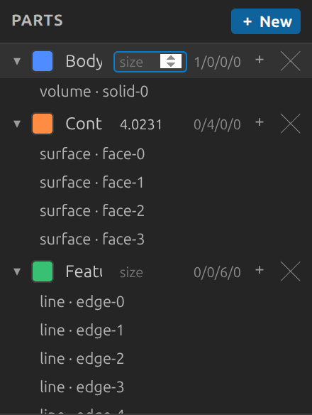
Parts are saved automatically to a <model>.parts.json sidecar next to the CAD file and reloaded when you reopen it — the CAD file itself is never modified. See Parts Sidecar for the format.
Mesh formats (STL/OBJ/PLY/glTF) have no stored face/edge topology. CAD Preview segments each mesh into connected, near-coplanar facets on load, so Surf picks a flat face (a cube → its 6 faces) and Vol picks the whole object. Highly curved meshes that would split into very many facets are kept whole; Line and Point are disabled for meshes.
Inserting Standard Parts
The Standard Parts panel (below Parts in the sidebar) searches the hosted step.parts catalog — fasteners, bearings, connectors, extrusions, and more — and inserts a result as an ordinary STEP file:
- Type a query (e.g. "M6 hex bolt") and click Search.
- Each result shows a thumbnail beside its name, description, category, and standard designation (thumbnails load lazily after the text — a result with no image simply shows its text). Click Insert… on one.
- A Save dialog appears, defaulting to
<part-id>.stepnext to the currently open document. Saving downloads the file (its checksum is verified against the catalog's own recorded SHA-256, when one exists) and opens it as a new tab; dismissing the dialog is a no-op.
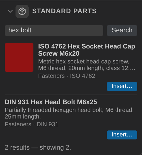
An inserted part opens as its own document rather than merging into whatever model you already had open — combine it with your existing model using the ordinary Editing Geometry tools (position it with Move/the Transform Gizmo, then Boolean/Mate it in) once both are open. This requires network access to api.step.parts; if the service is unreachable, the panel shows a clear status message rather than an error.
Editing Geometry
The Edits panel (below the Parts panel) applies non-destructive edit operations to the model. Edits never touch the CAD file — they are saved as an ordered, replayable op-list in a <model>.edits.json sidecar and re-applied each time you open the file.
Every parameter form previews live: while a form is open, the viewer shows what that op would produce as a translucent overlay, re-computed as you type (~250 ms debounce) and coloured by intent — green where material is added, red where it is removed, blue for wire/reference results (points, lines, sketch faces), neutral for transforms and fillet/chamfer. Switching forms or changing the selection cancels the preview; only Apply commits anything to the history.
The Extrude, Revolve, Shell, and Draft forms also carry a Pin query row: pick exactly one face, choose the producing op and bucket role it came from (e.g. an extrude's end cap), and click Synthesize to name that face as a stored query. The query is attached when you click Apply (as long as the selection hasn't changed since) and survives later edits renumbering the model's faces — the same mechanism agents use headlessly, now available interactively. Edge/volume operands and multi-face picks can't be pinned yet; the row says so rather than offering a dead button.
The panel is organised into two top-level tabs — GEOMETRY (create new entities) and EDIT (modify existing ones) — sharing one undo/redo/Clear header and one operation-history list. The GEOMETRY tab is further split into 2D (points, lines, curves, sketch profiles) and 3D (solid primitives, holes) subtabs. Each tab shows a grid of operation buttons (icon + name); clicking a button opens its parameter form below the grid, and clicking it again collapses the form. For mesh sources the whole 2D subtab and every other B-rep-only button grey out.
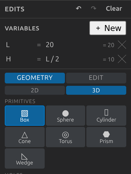
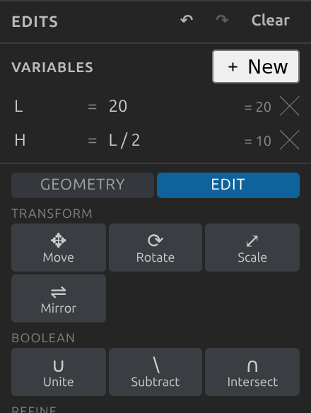
Left: GEOMETRY → 3D primitive creation. Right: the EDIT tab's modification ops.
To apply a transform:
- Open Select ▾, click Selection mode, choose Vol, and click one or more volumes (solids).
- In the Edits panel open the EDIT tab and pick an operation — Move, Rotate, Scale, or Mirror — and fill in the numeric fields.
- Click Apply. The model updates live and the operation is added to the list.
Transform Gizmo
Opening Move, Rotate, or Scale with a selection active also attaches a draggable 3D gizmo to the selected volume(s), centred on their shared bounding-box centre — dragging it is a live preview only (nothing is applied yet) and fills in the same numeric fields the form already shows, so typing and dragging stay in sync. Move shows a 3-axis arrow set (drag one to move along that axis only); Rotate shows rotation rings about the pivot; Scale shows drag handles. Selecting two or more volumes moves/rotates/scales them together as one rigid group, not independently. Orbit/pan is automatically suspended for the duration of a gizmo drag. Releasing the drag leaves the preview showing — nothing is added to the op list until you click Apply; switching to a different form, or clicking a different selection, discards an uncommitted drag and snaps the model back to where it was. Snap to grid and Snap to points (see View ▾ above) both apply live during a Translate drag.
GEOMETRY → 2D (all B-rep only; each is typed-in, no selection needed unless noted):
| Op | Action |
|---|---|
| Point / Line / Arc | Appends a standalone point / straight line / circular arc you can select later (Point/Line mode) |
| Polyline | Appends straight edges through an editable list of points (+ Add point / − rows); Closed adds the last→first edge |
| 3-Pt Arc | Appends the circular arc through three typed points (a collinear triple is skipped) |
| Spline | Appends a smooth curve through the point list (endpoint-exact fit) |
| Bezier | Appends a Bézier curve over the control-point list (passes through first and last only) |
| Ell. Arc | Appends an elliptical arc — Radius X along Up, Radius Y perpendicular, trimmed Start°→End° |
| Helix | Appends a helix: Turns revolutions of Pitch height around Axis from Base, radius Radius |
| Circle / Rectangle / Polygon / Ellipse / Rounded / Slot / Trapezoid | Sketch — appends a flat profile face you can later select (Surf mode) and feed into Extrude/Revolve/Sweep/Loft. Rectangle-family shapes take an Up direction for in-plane orientation. Circle/Rectangle/Polygon additionally offer a Plane picker: choose a saved plane-N to place the sketch from the plane plus Offset U/V (and Rotation° for rectangle/polygon), or leave it on Custom and type the center by hand — picked placement fills the coordinate fields in and locks them until you switch back |
| Surface (Build from selection) | Select ≥3 lines (Line mode) that close into a loop and Build — assembles them into a new flat face under "Sketches" |
| Edge Slot (Build from selection) | Select one edge (Line mode), enter a Width, Build — appends a stadium slot face around that edge (length = edge length + width) under "Sketches" |
| Construction (guide) checkbox | Every 2D profile/curve form offers one: the built entity is marked reference-only — rendered dimmed, still pickable/measurable, and refused as a profile operand by Extrude/Revolve/Sweep/Loft/Surface/Volume |
GEOMETRY → 3D:
| Op | Action |
|---|---|
| Box / Sphere / Cylinder / Cone / Torus / Prism | Add — appends a new body at that placement (no selection needed; all formats) |
| Wedge | Add — appends a right-angular wedge: base Size X×Size Y centred at Base ctr in the plane ⟂ Axis, extruded Height; the far edge narrows to Top X (B-rep only) |
| Hole / C'bore / C'sink | Select target volume(s) (Vol mode), place the mouth (Mouth + Axis pointing into the material), and Cut — drills a plain, counterbored, or countersunk hole (all formats). The Standard dropdown fills Radius (and, for a tapped size, a sensible blind Depth) from the ISO metric / UNC / UNF tables — pick e.g. M6 tapped or M6 clearance instead of looking the number up; the fields stay editable afterwards |
| Volume (Build from selection) | Select ≥4 surfaces (Surf mode) that close into a shell and Build — sews them into a new closed solid (B-rep only) |
EDIT:
| Op | Action |
|---|---|
| Move / Rotate / Scale / Mirror | Enter parameters, Apply to the selected volumes (all formats) |
| Unite / Subtract / Intersect | Select operand-A volumes and click Set A, then select operand-B volumes and click Apply (all formats) |
| Fillet / Chamfer | Select edges (Line mode), enter the radius / setback, Apply (B-rep only) |
| Extrude / Revolve / Sweep / Loft | Select a profile face (Surf mode; a path edge too for Sweep, 2+ faces for Loft), set parameters, Apply — builds a new body (B-rep only). Extrude/Revolve/Sweep also take Regions to narrow a multi-region profile (blank = face as modeled, all, or indices like 0,2). Loft takes an optional captured Rail (Set rail on 1+ Line-mode edges): resampled intermediates steer the surface through the rail — exactly 2 closed sections, no thinning |
| Shell | Select the opening face(s) (Surf mode), enter a wall thickness (negative = walls grow inward, the usual hollow), Apply — hollows the solid(s) owning those faces (B-rep only) |
| Draft | Select the face(s) to taper (Surf mode), enter an Angle° (0–90), and optionally a neutral-plane Point + Normal — leave both at 0 to taper each face about its own plane — then Apply (B-rep only). Known kernel limitation: the bundled OCCT WASM build's draft engine fails on real geometry (probed — see CLAUDE.md), so the op currently reports a "did not apply — kernel limitation" diagnostic in the history instead of changing the model; it will work without changes once the upstream build fixes it |
| Defeature | Select the face(s) to remove as recognized features — fillet bands, chamfers (Surf mode) — then Apply (B-rep only). The solid heals behind the removed faces; faces that bound no removable feature are left in place |
| Split | Select volumes (Vol mode), define the plane, choose which side(s) to Keep, Apply (B-rep only) |
| Section | Select volumes (Vol mode), define the plane, Apply — appends the planar cross-section as a sketch face, leaving the solids untouched (B-rep only) |
| Drill | Select volumes (Vol mode) plus a profile face (Surf mode) or wire (Line mode), set Dir/Length, Apply — cuts the profile's regions through the volumes. Regions narrows a multi-region profile: blank (face as modeled), all, or indices like 0,2 (0 = outer boundary) (B-rep only) |
| Rib | Select an open spine sketch (Line mode), set a wall Thickness and an Up-to face, Apply — extrudes the wall to that face (plus one thickness of embed), fuses it into the surrounding solids, and blends the junction (B-rep only) |
| Wrap | Select a flat sketch face (Surf mode) — a holed profile (e.g. an imported letter with a counter) is supported, its hole cut out of the developed shell — pick Cylinder or Cone target, set axis/radius (half-angle for cones) + wall Thickness and variant — Standalone appends the wrapped shell, Emboss fuses it into the target volumes, Engrave cuts it out (B-rep only) |
| Explode | Drag the slider (or type the factor) for a live preview — bodies spread radially from the model centre as you drag, snapping back at 0 — then Apply to commit it as an operation (all formats) |
| Mate | Select two faces (Surf mode): face A then face B, and Apply — aligns A onto B (B-rep only) |
| Align | Select volumes (Vol mode); choose an Axis (X/Y/Z), an Extent (min/center/max of each volume's own bounding box), and a target coordinate To; Apply — moves each selected volume along that one axis so its own chosen extent lands exactly on the target. Every targeted volume aligns independently, even when the whole model is selected (all formats) |
| Linear Pattern | Select volumes (Vol mode); set a Direction, a Spacing, and a Count (total instances, including the original); Apply — appends Count − 1 evenly-spaced copies of each selected volume (all formats) |
| Circular Pattern | Select volumes (Vol mode); set an Axis point + Axis direction, an Angle step, and a Count; Apply — appends Count − 1 copies arrayed around that axis at equal angular spacing (all formats) |
Reference helpers: the op model itself accepts references instead of typed coordinates — Mirror, Split, and Section can take midplaneFaces: [faceA, faceB] (two planar, parallel faces; the op acts on the plane halfway between them) and Circular Pattern can take midaxisOf: [cylA, cylB] (two cylindrical faces or two parallel edges), each mutually exclusive with the typed-in vectors. These are authorable headlessly via apply_edit_ops (see doc/mcp-server.md) and degrade with a clear diagnostic when the referenced faces are missing, non-planar, or not parallel; mesh files only accept the typed-in coordinates. Interactively, the Planes panel's Midplane… button (below the saved-plane list) builds a new named plane halfway between two already-saved ones — the same math, computed client-side.
Header controls: ↶ / ↷ undo / redo the last operation; Clear removes all operations (back to the original model). To remove one specific operation without discarding everything applied after it, hover its row in the history list and click the ✕ that appears — unlike Undo, which only pops the most recent operation, this removes any row directly. The history is also a clickable timeline: undone-but-redoable steps appear as dimmed rows with continued numbering, and clicking any row — applied or dimmed — rolls the whole stack straight to that point in one step (clicking a dimmed row re-applies through it).
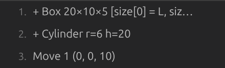
Transforms, booleans, explode, primitives, and the hole family work on both B-rep and mesh files; everything else is B-rep only (the panel disables those buttons — and the whole 2D subtab — for meshes). Creation ops append a new body to the model; holes are the exception — they cut into the selected volumes. For primitives, center is the body's geometric centre (box/sphere/torus) or its base centre (cylinder/cone/prism/wedge, extruded along Axis) — matching how the underlying CAD kernel places them. A 2D profile sketch builds a flat face, not a body — it's meant to be picked and extruded/revolved/swept/lofted; doing so consumes the sketch into the new solid rather than leaving a duplicate flat face behind. Building a Surface or Volume needs an already-closed selection (a loop of lines, a sealed set of surfaces); an open selection is silently skipped rather than producing a malformed body — the same graceful-skip rule every op follows when its inputs don't resolve.
The operation buttons' icons are placeholder glyphs — they live in one file, src/webview/opIcons.ts, made to be swapped for real icons.
When you Export an edited model, the edits are baked into the output file. See Edits Sidecar for the format.
Parametric Variables
The Variables table at the top of the Edits panel makes the model parametric: define named values once, reference them in any numeric field of any edit operation, and change them later to rebuild the geometry on the fly.
- Click + New in the Variables header. A variable appears with an auto-generated name (
L1, …) — rename it inline and set its expression (e.g.20). The computed value shows to the right of the row. - In any op's parameter form, type the variable name — or an arithmetic expression like
L/2 + 1— instead of a number, then Apply/Add as usual. The op is created with the current value and remembers the expression (the history line shows it as[length = L/2 + 1]). - Edit the variable's expression in the table — every operation referencing it re-resolves and the model rebuilds immediately.
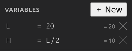
Expressions support numbers, variable names, + - * / ^, parentheses, sqrt/abs/min/max/floor/ceil/round, sin/cos/tan (degrees, matching the angle fields), and pi. A variable's own expression may reference the variables defined above it in the table (so W = L/2 works; reordering isn't supported). Because the fields are free-text, they no longer have browser spinner arrows — type the value.
If an expression can't be evaluated at Apply time (unknown name, syntax error), the apply is blocked with an inline message. If a referenced variable is later deleted or renamed, affected operations keep their last computed values — a warning names the missing variable, and re-adding it restores the parametric link. The delete button's tooltip warns when a variable is still referenced. Variables persist in the same <model>.edits.json sidecar as the operations (format); variable edits are not part of the op undo/redo history.
Generating an FE Mesh
The FE Mesh panel (below the Edits panel) generates a finite-element mesh (nodes + triangles/tetrahedra) of the currently displayed model using Gmsh compiled to WebAssembly. The result is shown as a blue overlay on top of the existing geometry — it never replaces or modifies the original model. See GMSH Integration for the full technical write-up.
To generate a mesh:
- Pick a target element size with the coarser→finer slider (or a Coarse/Medium/Fine preset). The default is derived from the model's bounding box (diagonal / 20), and the readout above the slider shows the current size plus a rough estimate of how many elements it will produce (the preset nearest the current size is highlighted). Fine-grained options (dimension, algorithms, element shape, element order, …) live in the collapsed Advanced settings section.
- Click ▶ Generate (the full-width button at the top of the panel; the header shows the element count once a mesh exists). The overlay appears and the panel's status line shows
Nodes: N · Elements: M · 3.2 s, or an error message if generation fails. Below the status line, a quality summary reports the minimum and mean element quality (Gmsh'sminSICNmetric, 0–1, higher is better) plus a small histogram of the distribution — useful for spotting a generate that technically succeeded but produced a lot of sliver elements. If any elements scored below 0.20 (for a 3D mesh), a Worst button appears next to Clear and lights up automatically, highlighting those elements in bright red — visible even where they're buried inside the model, so you don't need to clip or cut away anything to find them. - Click FE Mesh in the toolbar to show/hide the overlay without discarding it; click Worst to show/hide just the worst-element highlight; click Clear in the panel to remove everything.
While a mesh is generating or exporting, the panel shows Cancel beside Generate. It cancels work for the current document/request; another open CAD document's queued or active mesh job is unaffected.
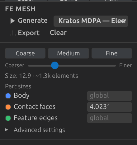
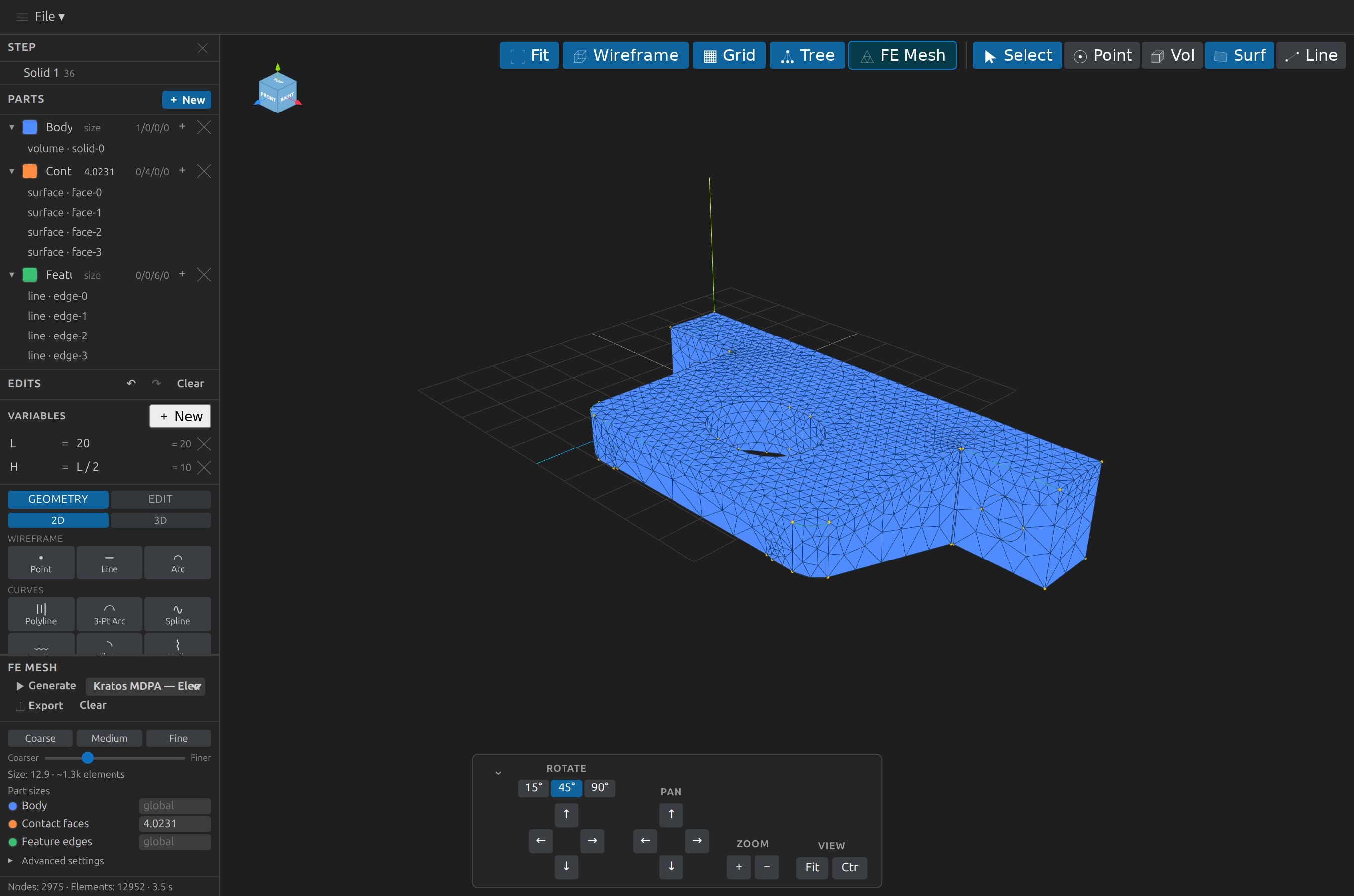
The FE Mesh panel and a generated 3D tetrahedral overlay (Nodes: 2975 · Elements: 12952), colour-scoped by part.
| FE Mesh control | Action |
|---|---|
| Deviation (gap icon beside Generate) | Generates with the current options and measures how far the mesh boundary strays from the CAD surface — geometric fidelity, which element quality can't show (a flattened fillet, a bridged gap, a dropped face). The boundary is coloured by each vertex's distance (viridis, 0 → worst), and the status line summarizes the worst deviation, p95, the fraction of the CAD surface within tolerance, the worst CAD face, and any extraneous surface. Set the tolerance under Advanced settings (Deviation tolerance, blank = 1/1000 of the model diagonal). Sampled against the CAD's own fine tessellation — an estimate, not a certified maximum. Headless: measure_mesh_deviation |
| Coarser→finer slider | The primary control: sets the target element size (Mesh.MeshSizeMax), log-scaled between bbox-diagonal/5 (coarsest) and /200 (finest). The readout shows the size and an estimated element range, computed from the displayed model's real volume and surface area in a model calibrated against real Gmsh runs (±25% on the calibration corpus); hover it for node count, a rough memory range, the confidence (calibrated, rough when the size is coarse relative to the part, uncertain with Part sizing/grading, hex-dominant or fTetWild) and the assumptions. A warning appears when the estimate exceeds ~1M elements, or your Element budget (advisory) from Advanced settings — it warns, never blocks. An open (non-watertight) mesh shows the size only: a volume count can't be estimated for it |
| Coarse / Medium / Fine | One-click presets: element size = bbox diagonal / 10, / 20 (the default), / 50 |
| Saved presets | (Sits beside Engine, with Apply · Save… · Delete on the PRESET label's own line.) Named, reusable option bundles (global settings only — Part sizing stays in the document): a picker over your own cad-preview-mesh-presets.json (beside the model, shared by every model in its folder) plus the built-in starters (coarse-preview, balanced, fine-detail, robust-repair). Apply writes the preset's options — sizes converted from its authored unit into mm — as the document's settings (nothing is generated); Save current… records the current options (prompts for a name); Delete removes your own preset (built-ins show no Delete button). Fields the preset's engine ignores are reported, not silently dropped; preset names describe density intent, never a mesh-quality guarantee. The same library is visible to list_mesh_presets / apply_mesh_preset headlessly. A preset may also carry an optional stlExport block (targetCellSize, chordalFraction, angularDeg, in the preset's unit) — the mesh-aware STL tolerance that export_tessellated_stl's preset parameter applies; the three built-in Gmsh starters carry one matching their target size |
| Part sizes | One size input per defined Part (visible once parts exist) — the only place a Part's target size is edited (shown to three significant figures; hover for the exact value); blank inherits the global size. A Grade toggle beside each part reveals a distance-graded band (Wall size / Far size / Near dist / Far dist): elements stay at the wall size within the near distance of the part's own entities, grow to the far size at the far distance, and stay there beyond it — for meshing toward a wall, unlike the flat size which only refines inside the part. B-rep sources only |
| Engine | Gmsh (default) or fTetWild — an alternative volume mesher for a dirty mesh-format 3D source (holes, self-intersections, non-manifold edges) that Gmsh's own boundary reclassification rejects or silently produces no elements for. Under fTetWild, Size min / 2D-3D algorithm / Element order / Element shape / STL angle are all greyed (unused); the size slider still applies, via fTetWild's own envelope/target-edge-length settings under Advanced, plus three optional flags: manifold surface (force a manifold boundary), coarsen (fewer, larger tets), and no interior filter (skip interior/exterior filtering — returns a hull fill, not the part interior; inspection only). Requesting fTetWild for a B-rep source or a non-3D dimension falls back to Gmsh automatically |
| Advanced settings (collapsed) | The raw Gmsh options below — expand to reveal them (shown here). The export row (format · unit · Export) always closes the panel, below this section |
| Dimension | 1D (edges only), 2D (surface triangulation), or 3D (volume tetrahedralization) |
| Size min / max | Bounds on generated element size (Mesh.MeshSizeMin/Mesh.MeshSizeMax); Size max is the same value the slider drives, shown numerically (clearing it restores the bbox-derived default) |
| 2D algorithm / 3D algorithm | The Gmsh meshing algorithm to use for each dimension |
| Element shape | Triangles / Tetrahedra (default), Quads / Hexahedra (recombines the mesh into quadrilaterals in 2D / hexahedra in 3D), or Hex-Dominant (3D) (a mixed tet/hex mesh via Gmsh's RTree recombiner — not exportable to Kratos MDPA, use a different export format) |
| Element order | Linear (1) or quadratic (2) elements — quadratic adds mid-side nodes (the overlay still draws the corner geometry) |
| Optimize | Run Gmsh's mesh optimizer after generation |
| STL angle (°) | Surface-classification angle for mesh/STL sources (disabled for B-rep documents, which never reclassify) — only used by engine: Gmsh |
| fTetWild envelope (eps) | fTetWild's envelope size, as a fraction of the model's bounding-box diagonal — smaller stays closer to the input surface (slower). Only used by engine: fTetWild |
| ▶ Generate | Run Gmsh now with the current options and show the result as an overlay |
| Cancel | While Generate/Export is active, cancel only the current document/request's queued or running meshing work |
Export format <select> | Pick which format 📤 Export writes — Kratos MDPA (Elements + Conditions) (the default), Kratos MDPA (Geometries), Gmsh Mesh (.msh), Gmsh Mesh v2/Legacy (.msh2), Gmsh Geometry (.geo_unrolled), VTK, MED, CGNS, XDMF, I-DEAS Universal (.unv), Abaqus (.inp), Nastran Bulk Data (.bdf), SU2, INRIA Medit (.mesh), STL Mesh, Diffpack (.diff), OFF, VTK XML Unstructured (.vtu), HDF Mesh Format (.hmf), AVS UCD (.avs), COMSOL Mphtxt (.mphtxt), Netgen (.vol), FLAC3D (.f3grid), Well-Known Text (.wkt), or Flux (.pf3). Both Kratos MDPA modes preserve named Parts as Kratos SubModelParts and support linear or quadratic tetrahedra/hexahedra/triangles/quadrilaterals. MED/CGNS/XDMF and the 8 trailing formats (VTU through Flux) are all bridged through meshio++ (this Gmsh build has no writer for any of them) — MED preserves named Parts as named MED groups, and XDMF also writes a companion .h5 file alongside the .xdmf. |
Export unit <select> | A real geometric scale applied to the exported file's geometry before Gmsh sees it — mirrors the model Export command's own unit picker (see Units). Defaults to mm (native, no conversion); Size min/max and any per-part mesh size or grading band are automatically rescaled to match, so relative mesh density stays the same regardless of the chosen unit. Only affects 📤 Export — ▶ Generate's overlay always meshes at native mm, since it has no exported file for a unit to matter to. |
| Handoff manifest checkbox | Under the export row. When ticked, Export also writes <output>.handoff.json beside the saved mesh: the source file's hash and edit-history fingerprint, the effective options, unit and scale, the engine and kernel versions, the hashes of every written file, and how each Part landed in the mesh (physical groups, SubModelPart sizes, and which Parts are empty or resolved to nothing, plus surfaces in no group and overlaps). A status line summarizes the coverage. The check_handoff_manifest MCP tool tells you later whether the manifest still describes the model. Costs one extra meshing pass. |
| 📤 Export | Mesh with the current options (at the chosen export unit) and save the result in the format picked above, via a Save dialog (independent of whether ▶ Generate was already clicked — it always (re)generates fresh) |
| ⚠ Worst | Only shown after a 3D generate with at least one element below quality 0.20 (auto-shown then, since it's a warning). Toggles the worst-quality-elements highlight in place, without discarding it |
| Clear | Remove the mesh overlay and the worst-elements highlight (the original model is unaffected either way) |
| Refinement sweep | Collapsed by default. Enter up to 8 mesh sizes in mm (4, 2, 1) and click Run sweep to mesh the current geometry at each size with the panel's other options — the interactive compare_mesh_refinement. A table shows each run's nodes, elements, time and min/mean element quality (a failed size is its own row, with its error); Copy TSV copies the same tab-separated table the MCP tool returns. Tick Write each mesh (.msh) to a folder to be asked for a folder and get one <name>-size-<size>.msh per run. Cancel (greyed out until a sweep is running) stops a long sweep: the runs already finished are kept and shown, the size that was being meshed is simply left out, and the status line says the sweep was cancelled — so a short table is never mistaken for a complete comparison. The note under the table says what the numbers do not show: finer meshes and better element quality do not prove the FE solution has converged — that needs a solver. The panel's own options are never changed. |
| Mesh ops | Only shown for a meshio++-imported source (VTK/MED/CGNS/…). One operation per Run op… — Clean, Decimate, Smooth, Subdivide, Refine, Agglomerate, or Convert cells — with only that op's parameters shown. Writes a NEW file via a Save dialog (same format as the source); the open document is never modified. The per-step applied/skipped report renders in the section's status line |
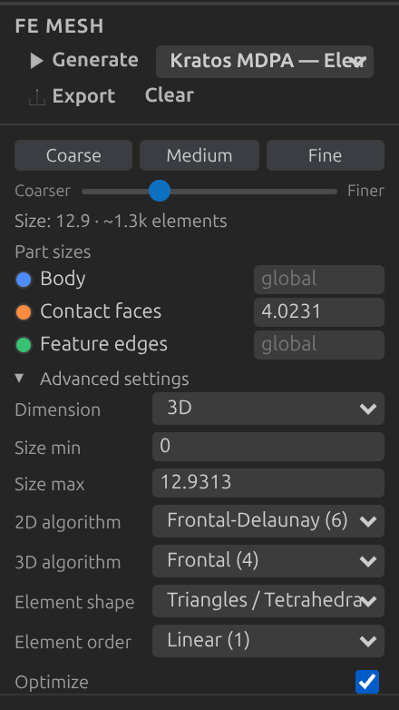
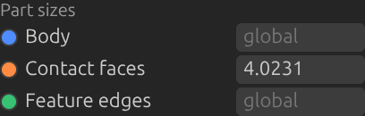
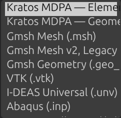
Left: per-part local sizing. Right: the mesh export-format picker (Kratos MDPA is the default).
Mesh options are saved automatically to a <model>.mesh.json sidecar next to the CAD file, and an editable <model>.geo Gmsh script is regenerated alongside it on every change — see Mesh Options Sidecar for the format. The .geo file is one-way: hand-edits to it are never read back by the extension — use the FE Mesh panel to change options, not the generated script. Neither file modifies the source CAD file.
B-rep vs mesh sources: for STEP/IGES/BREP files, the model currently shown (including any applied edits) is re-exported to STEP and handed to Gmsh directly. For STL/OBJ/PLY/glTF files, Gmsh has no volume topology to start from, so the displayed triangle soup is first reclassified into surfaces at sharp-angle boundaries (
classifySurfaces, default 40°) and rebuilt into a closed volume before a 3D mesh can be generated.
Mass Properties
The Mass Properties panel (below the FE Mesh panel) computes volume, surface area, length, center of mass, and moments of inertia for the whole model or a single selected entity.
- With nothing selected, click Compute for whole-model properties. To inspect one entity instead, enter Select mode, pick exactly one volume, surface, or edge, then click Compute — selecting more than one entity shows a guidance message instead of a (possibly misleading) combined result.
- The panel shows whichever fields apply: a volume/solid gets Volume, Area, Center of mass, and Ixx/Iyy/Izz; a single face gets Area only; a single edge gets Length only.
For STEP/IGES/BREP files this runs in the extension host via OpenCascade.js's BRepGProp; for STL/OBJ/PLY/glTF files it's computed entirely in the webview from the displayed triangle mesh (no moments of inertia for mesh sources in this first cut). Volume/Area/Length/Center of mass are labeled and shown in whatever unit the view-controls Units dropdown is set to (see Units above) — switching it live-rescales an already-computed result with no need to click Compute again; Ixx/Iyy/Izz are always shown raw, unaffected by that setting.
Clash
The Clash panel (below Mass Properties, B-rep sources only) checks Parts against each other for real volumetric overlap via exact B-rep booleans — the interactive counterpart of the check_interference / check_interference_all MCP tools.
- Pick two Parts in the dropdowns and click Check for a pairwise result, or click Check all to test every Part with assigned solids against every other in one call.
- Each result row reads
A × B→overlap <volume>orno overlap. Pairs the AABB pre-filter decided without a boolean carry anAABB-screenednote; genuinely touching Parts (shared face, zero volume) correctly report no overlap. Volumes follow the Units dropdown like Mass Properties, live-rescaled on change.
Results are session-only and clear on every model rebuild, since re-tessellation may renumber the ids they name.
B-rep Health
The B-rep Health panel (Advanced ▸ Analysis, STEP/IGES/BREP sources only) runs OpenCascade's own validity checker (BRepCheck) on the model as currently edited. It reports facts, not a verdict of its own, and repairs nothing.
- Click Check. On a large model this takes a few seconds (about 9 s for a 2.3 MB STEP file).
- The summary line gives OCCT's whole-shape verdict (
valid per BRepCheckorINVALID per BRepCheck), the number of flagged subshapes and the number of open-boundary edges. - Below it: solid/shell/face/edge counts, one row per solid (shells and how many are open), and one row per flagged subshape with the checker's named statuses — for example
face-13 — UnorientableShapeorshell-0 — NotClosed. Hover a face, edge or solid row to highlight it in the view.
shell-N ids are local to this report; nothing else in CAD Preview names shells. A model that passes is not guaranteed to mesh in Gmsh — the checker and the mesher test different things. The same report is available headless as the check_brep_health MCP tool.
Passages
The Passages panel (below Primitives, B-rep sources only) is a pre-meshing check for narrow channels a mesh could fail to resolve even with good element quality. Set cells (how many elements you want across a passage, default 3) and click Analyze. It finds two shapes, from the exact CAD faces:
- an annular gap between two coaxial cylindrical faces (a rod in a bore) — width is the radial difference, and the faces must overlap along the axis (merely coaxial cylinders at different heights are not a passage);
- a slot between two parallel flat faces facing each other — width is their distance, and they must genuinely overlap.
Only gaps of empty space count — the two faces of a wall are never reported. Each row shows the width, roughly how many cells the current size puts across it (from the smallest Part size on either face, else the FE Mesh global size) and the size that would give your target; hovering a row highlights both faces. Under-resolved rows (warning colour) offer Apply local size, which creates or updates a Part named Passage face-A/face-B on the two faces with that mesh size — an ordinary Part, so it persists, rebinds, and shows in FE Mesh › Part sizes. These are estimates; generate a mesh to confirm. Headless: analyze_passages, then set_part.
Primitives
The Primitives panel (below Region fit, B-rep sources only) classifies each solid as a box, sphere, cylinder, cone, or torus — the interactive counterpart of the recognize_primitives / decompose_to_primitives MCP tools.
- Click Recognize for a read-only per-solid report: face inventory by surface type, the candidate primitive with its key dimensions, and the fit residual (absolute and as a fraction of the solid's size) — or an honest "not a recognized primitive" for anything that doesn't match a signature exactly (e.g. a filleted box), never a guess.
- With at least one solid recognized, Apply as edits pushes one parametric creation op per recognized solid (each dimension bound to a named variable) onto the edit history — undoable, removable op-by-op like any hand-applied edit. Export… writes the same ops as a brand-new STEP/IGES/BREP file (format + unit picks, then a save dialog — the source file is untouched). Save macro… stores them as a reusable parameterized macro in the folder's
cad-preview-macros.json.
The report is session-only and clears on every model rebuild, since re-tessellation may renumber the solids it names.
Exporting a Model
Pick File ▸ Export… (or press Ctrl+E) to convert the open model and save it as a different file. The list of offered target formats depends on the file you opened:
| You opened | You can export to |
|---|---|
| STEP, IGES, or BREP | its own format (save in place, see below) plus the other two B-rep formats, plus STL, OBJ, PLY, and glTF |
| STL, OBJ, PLY, or glTF | the other mesh formats only |
The format you opened is never offered as an export target — except as a same-format B-rep pick, which is a save in place, not an export. Picking your own format (STEP→STEP, IGES→IGES, BREP→BREP) asks for an explicit modal confirmation and then writes the edited model back to the open file itself: the op list is baked into the file (via a temp sibling + rename, with a one-deep <model>.bak written on the first save of the session), the sidecar keeps the full history with the baked prefix marked, and replay continues after it. A re-emitted file preserves assembly structure and part names but not entity numbering, authoring metadata, or per-part colour; it is saved at the file's own declared unit. Undo cannot cross the save point. Mesh sources (STL/OBJ/PLY) can also be saved in place this way; glTF and meshio/CAD-text sources cannot (no same-format writer). A save that is interrupted mid-way is recovered on the next open for mesh sources — see Known Limitations. Picking any target format opens a second quick-pick asking for an export unit — "Native (mm) — no conversion" is first and pre-highlighted, so pressing Enter immediately exports unchanged; picking cm/m/in/ft instead applies a real geometric scale to the exported file (not just a display change — the model reopens at the new size). This applies to every target, STEP and IGES included — both correctly relabel their own declared length unit to match the converted geometry, not just scale the numbers while leaving the header saying millimetres. Pressing Escape on this step also exports natively rather than cancelling. A native Save dialog then lets you choose the destination — it defaults to the source file's folder with the new extension. glTF export always produces a single binary .glb file (no separate .bin/texture references to manage).
B-rep targets are converted by OpenCascade.js's own writers, so STEP ↔ IGES ↔ BREP round-trips preserve true CAD geometry, not just a tessellated approximation. Mesh targets are generated from the triangulated geometry already shown in the viewer — there is no way to turn a mesh file (or a tessellated B-rep) back into precise CAD surfaces, which is why mesh sources can't export to STEP/IGES/BREP.
Mesh-aware STL. Exporting a B-rep source to STL adds one more (optional) quick-pick after the unit: As displayed (the viewport's tessellation, the default and what Escape picks) or Mesh-aware…. A downstream volume mesher cannot recover curvature an STL already lost, so mesh-aware asks for the downstream cell size (in the export unit) and a chordal fraction (default 0.1): the tessellation's chordal tolerance is their product, with a 20° angular limit, independent of the viewport. The status line previews the triangle count before the save dialog, and after writing reports the sampled chordal error actually achieved (centroid and edge midpoints of a sample of triangles, measured against the exact CAD face) — an estimate, not a certified maximum. A tolerance that would produce more than two million triangles is refused before anything is written. Planar faces are never over-refined; the physical tolerance is the same whichever unit you write.
Exporting a Silhouette SVG
Pick File ▸ Export Silhouette SVG… (or Export Silhouette DXF… for the DXF variant; both also exist as CAD Preview: Export Silhouette … commands) to write a 2D outline drawing of the model as an .svg or .dxf file.
For a drawing that shows what is behind the part, pick File ▸ Export Technical Drawing… instead. That one runs hidden-line removal: it draws interior feature edges as well as the outline, and renders anything occluded as a dashed line — so a through-hole's far rim appears dashed rather than missing. It shares the same view and unit picks, and writes SVG or DXF (where hidden geometry goes on a HIDDEN layer you can toggle in a CAD tool). It is still a single view — treat it as a review or illustration artifact and measure anything you need to be sure of, though any measurement you've pinned (see Measuring) still bakes in as a dimension glyph. This is separate from the Export… flow above — an outline is a drawing, not a 3D model, so it never appears in that quick-pick's target list.
- Pick a view. The first entry is Current view — the angle you are currently looking at — followed by Front, Back, Top, Bottom, Left, Right, and Iso. Pressing Escape here cancels the export.
- Pick an export unit. The same quick-pick every other export shows, defaulting to native mm; Escape here still exports (at mm), it doesn't cancel.
- Choose a destination in the native Save dialog (the menu item you picked decides SVG vs DXF and the default extension).
It's an outline, not a dimensioned 2D technical drawing — there is no hidden-line removal. Back-facing geometry isn't drawn, but neither are interior feature edges that don't lie on a silhouette (a hole seen face-on draws as a circle; the same hole seen edge-on draws nothing). OpenCascade's hidden-line machinery is entirely unavailable in the bundled WASM build, so the outline is derived from triangle adjacency instead — which is also why this works for mesh files, not just B-rep. Use it for review notes, documentation figures, and laser/plotter outlines; use the Measurement tools for any dimension you need to be sure of.
Works for STEP/IGES/BREP (with your edits baked in, from the current tessellation) and STL/OBJ/PLY/glTF (from the raw file — edits are not baked in, since mesh edits can't be replayed outside the viewer). meshio-only sources (VTK/VTU/MED/CGNS/Exodus/XDMF/MDPA/Gmsh Mesh/Abaqus/I-DEAS Universal/SU2/INRIA Medit/Nastran) are rejected.
Exporting a Drawing Sheet
Pick File ▸ Export Drawing Sheet… (or CAD Preview: Export Drawing Sheet…) to place several views of the model on one sheet — the ordinary output of a drafting workflow, rather than one file per view.
A settings form opens with every choice on one page:
- Template — pick a saved or built-in template (
iso-a3-first,asme-a3-third,front-fit-1to1) to fill the form; Save as template… stores the current settings (asks for a name) incad-preview-sheet-templates.jsonbeside the model, shared by every model in that folder and by theexport_drawing_sheetMCP tool. - Views — any of the named views, in any combination.
- Projection — first-angle (ISO, default) or third-angle (ASME).
- Paper — Fit sizes the sheet to the views; A4 through A0 (landscape) use the scale below or, on Auto, the largest ISO 5455 standard scale (50:1 down to 1:1000) that fits, warning rather than silently clipping if nothing fits.
- Scale — Auto, a standard ratio, or Custom (any ratio like
3:4). - Title block — title (default the file name), drawn by, drawing number, revision and material; each field adds a cell only when filled.
- Format — SVG or DXF.
Export… then asks for a destination. There is no unit step: a sheet's scale ratio is only meaningful against the model's own millimetres. The form remembers your last settings for the session.
The default four views — Front, Top, Right, Iso — are laid out orthographically: first-angle projection (the default, and the ISO convention) places the top view below the front view and the right-side view to its left; third-angle (ASME) mirrors both. Each view is a technical drawing like the single-view export above — hidden edges dashed (SVG) or on a HIDDEN layer (DXF) — inside a title block naming the model, the scale ratio, the projection method, the date, and the views shown.
A pinned annotation is drawn once, in whichever orthographic view shows its measured line at true length rather than foreshortened — an edge running front-to-back reads true in the Right view and appears nowhere else on the sheet. Works for the same source formats as the single-view exports above.
The MCP server exposes the identical capability as export_drawing_sheet (plus save_sheet_template / list_sheet_templates) — both paths resolve settings through the same code, so identical settings produce identical sheets. See doc/mcp-server.md.
The SVG output is a single self-contained <path> with no external references, at 1 SVG user unit = 1 model unit and a physical size in millimetres — so a drawing exported from a native (mm) model prints 1:1 in any vector tool. The DXF output is minimal model-space ENTITIES: chained collinear outline runs become LWPOLYLINEs and unmatched singletons stay independent LINEs. One caveat: the outline depends on consistent triangle winding, so a mesh with mixed winding (as some exporters and hand-edited files produce) draws spurious interior lines.
Batch export
Run CAD Preview: Batch Export… from the Command Palette to export many files at once without opening them: pick the files, a target (STEP, IGES, BREP, a one-view SVG/DXF technical drawing, or an SVG/DXF drawing sheet), a destination folder, and what to do when an output already exists (skip, add a numeric suffix, or overwrite — an input file is never overwritten). Files run one at a time with a cancellable progress notification; a file that fails becomes a failed row and the rest still export. A report panel lists every file with its status, output, how many edits were baked in (B-rep sources bake their whole edit history; a mesh source's drawing bakes its pending edits through the same engine the viewer replays with), and any error or warning. The same batch is available headlessly as the batch_export MCP tool.
Preparation report
Run CAD Preview: Preparation Report… to write a one-stop summary of a model's preparation facts: report.json plus a self-contained report.html (no scripts, no network — safe to mail or archive). It uses the focused tab (saving its sidecars first), or asks for a file when none is focused, then asks for a destination folder. Sections cover source identity (file hash and edit fingerprint), the effective mesh options, edit replay, mass properties, BOM, hole table, mesh health, narrow passages, the budget estimate beside the actual generated mesh, and — through the generate_prep_report MCP tool — deviation, a handoff-manifest check and snapshots. Every section says whether it ran, and if not, why; nothing is silently left out. Mesh-format sources' inspection facts describe the raw file (their pending edits are not baked into them); the meshing sections bake those edits first.
Comparing Models
Run CAD Preview: Compare Models… from the Command Palette to diff two STEP/IGES/BREP, STL, OBJ, PLY, or glTF/GLB files (any combination) solid-by-solid — useful for checking what actually changed between two versions of a model. If a CAD Preview tab is focused when you run the command, its file is used as model A automatically and you're only prompted for B; otherwise you're prompted for both.
A results tab opens beside the editor showing:
- Matched solids (present in both, paired up by bounding-box-centroid proximity and volume similarity) — each row shows its centre displacement and volume delta, so you can tell a solid that just moved slightly from one that was heavily reshaped, rather than trusting a single "changed" verdict.
- Removed solids — present only in A.
- Added solids — present only in B.
This is a display-only report (no 3D view, no merge) — to actually look at both models side by side, open each in its own tab and use VS Code's split editor layout. STEP/IGES/BREP, STL, OBJ, PLY, and glTF/GLB are all supported, in any combination; the meshio-only formats (VTK/VTU/MED/CGNS/Exodus/XDMF/MDPA/OpenFOAM/Gmsh Mesh/Abaqus/I-DEAS Universal/SU2/INRIA Medit/Nastran) are the one remaining exception, since they never expose a triangle array outside their own WASM module. For a STEP/IGES/BREP file, the comparison reflects its currently-applied edits (its .edits.json sidecar, if any); for an STL/OBJ/PLY/glTF file, edits are not baked in (there's no way to replay a mesh edit outside the viewer) — a warning banner says so if the file has pending edits, and the comparison runs against the raw file as-is.
Known Limitations
- No texture support for OBJ. MTL material files are not loaded; a default grey material is applied.
- No glTF animations. Animation playback is not implemented — only the first frame (bind pose) is shown.
- No BRep-embedded geometry in glTF. Only triangulated
meshprimitives inside glTF are rendered. - No Compare Models / Mesh Health support for the meshio-only formats. STEP/IGES/BREP/STL/OBJ/PLY/glTF are all supported (any combination) — glTF included since a dedicated host-side parser shipped, cross-validated against three.js's own
GLTFLoader. VTK/VTU/MED/CGNS/Exodus/XDMF/MDPA/Gmsh Mesh/Abaqus/I-DEAS Universal/SU2/INRIA Medit/Nastran remain excluded: meshio++'s WASM module converts them to a boundary surface for display but never hands a triangle array back to JS, so there's nothing for the host to match on (they still open and preview normally). - Compressed glTF isn't parsed host-side. A
.gltf/.glbrequiringKHR_draco_mesh_compressionorEXT_meshopt_compressionis rejected with a clear error by Compare Models / Mesh Health / Promote to B-rep / Silhouette SVG — the host-side parser can't decode compressed buffers. Viewing such a file in the 3D view is unaffected. - Mesh Health and Promote to B-rep cap out at 50,000 triangles. Both build one OCCT face per triangle and sew them, so a larger mesh is refused with an actionable error rather than exhausting the WASM heap. Most likely to come up with glTF, a rendering-oriented format whose real-world files are routinely far larger than hand-authored STL/OBJ/PLY — tick the panel's Auto-decimate checkbox (decimates to ~1000 triangles first; the report says so, never silently), or use the Mesh Health panel's Repair (robust)… button (fTetWild-based, no equivalent triangle-count ceiling), if you hit it. Repair (robust)… writes a NEW watertight STL file — tetrahedralize the source with fTetWild, keep the resulting volume mesh's own boundary — enabled once Check Healability shows at least one component that did NOT close; re-running Check Healability / Promote to B-rep on the repaired output then typically succeeds where the original could not.
- Silhouette SVG/DXF draws an outline only. For hidden lines (occluded edges dashed) use File ▸ Export Technical Drawing…, and for several views on one sheet with a title block use File ▸ Export Drawing Sheet… — see Exporting a Silhouette SVG and Exporting a Drawing Sheet.
- Large assemblies are slow. STEP/IGES files above ~50 MB may take several seconds to tessellate. Tessellation runs in a forked kernel worker process, one shared by every open document — there is no streaming.
- One-time WASM startup. The first B-rep file open triggers OpenCascade.js initialization (~300 ms on a typical machine). Subsequent B-rep files open faster because the kernel is memoized.
- Source CAD file is written only by an explicit save. Ctrl+S (or Save All / auto-save) on a dirty tab bakes the unbaked op tail into the open STEP/IGES/BREP/STL/OBJ/PLY file itself (confirmed until the session's first bake, then on the dirty dot alone; temp-file + rename, one-deep
.bak, history watermark — undo cannot cross the save point, andFile: Revert Filedrops back to it). Export to another format writes a new, separate file; picking the source's own format in the Export flow saves in place behind its own modal confirmation. Part definitions are saved to a<model>.parts.jsonsidecar; pinned measurements to a<model>.annotations.jsonsidecar; and edit operations to a<model>.edits.jsonsidecar — the original geometry is otherwise always left untouched. Edits are non-destructive and replayable, and are baked in on save or Export. - An interrupted mesh save is repaired on the next open, but a B-rep one is not. A save writes the geometry and then advances the edit history's save watermark. If the process stops between those two writes, the file is baked while the history is stale — and reopening would replay the same edit over geometry that already contains it. For STL/OBJ/PLY a
<model>.save-journal.jsontransaction marker makes that recoverable: on the next open the save is either completed (the file provably holds the saved geometry) or discarded (the file was never rewritten), and if it matches neither — a half-written file, or something else editing it in the meantime — nothing is guessed and you are asked whether to restore<model>.bak. For STEP/IGES/BREP there is no such marker: the only protection is that a failed save rolls the file back, so a hard crash (kill, power loss) in that window still needs you to save again. See Exporting a Model.